
Delmar's Standard Textbook Of Electricity
7th Edition
ISBN: 9781337900348
Author: Stephen L. Herman
Publisher: Cengage Learning
expand_more
expand_more
format_list_bulleted
Related questions
Question
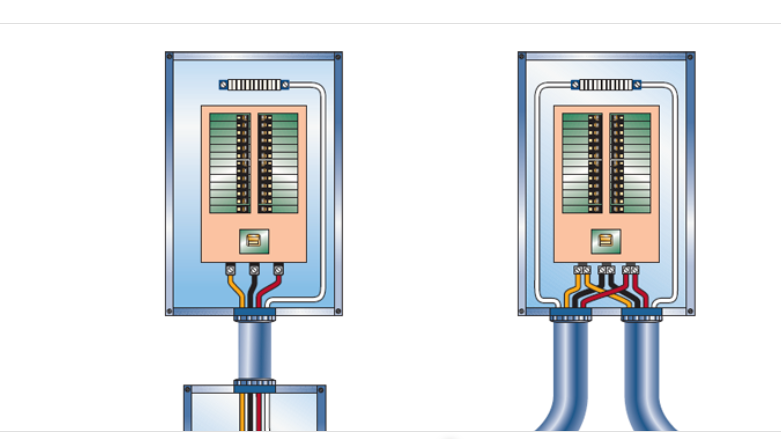
Figure 4-2 illustrates two methods of feeding a panelboard from a feeder that continues on to serve other loads. Compare the two methods and indicate your preference.

Expert Solution
This question has been solved!
Explore an expertly crafted, step-by-step solution for a thorough understanding of key concepts.

Step by stepSolved in 2 steps

Knowledge Booster

Similar questions
- Pls show neat and whole solutionarrow_forwardFor the circuit shown, the battery has a voltage of 13 V, the resistor has a resistance of 100 Ω, and the diode has a zener voltage of 6 V. Determine the maximum current iL that can be supplied to the load while the diode regulates the current. voltage. NEED A NEAT HAND WRITTEN SOLUTION WITH EXPLANATION ONLY OTHERWISE WILL LEAVE A DOWNVOTE..arrow_forwardA galvanometer with a internal resistance of 400 and a shunt resistor of value 'Rsh' is connected in series with a 100 resistor. A constant voltage VO' is applied aoross the oircuit, and the galvanometer deflects a certain amount. The shunt resistor is then removed, and replaced in series with the 100 resistor. With the same voltage 'VO', the galvanometer deflection is unchanged. Calculate the value 'Rsh' of the shunt resistor.arrow_forward
- Needs Complete solution with 100 % accuracy.arrow_forwardParts a & b pls.arrow_forwardUsing the diagram below and the component photos from page 4, draw the realistic experimental setup you will use in this lab. Draw the actual apparatus with wires and other electrical elements, connected as they will be on your lab table. Be sure to label components, junctions, and distances as appropriate.arrow_forward
arrow_back_ios
SEE MORE QUESTIONS
arrow_forward_ios
Recommended textbooks for you
- Delmar's Standard Textbook Of ElectricityElectrical EngineeringISBN:9781337900348Author:Stephen L. HermanPublisher:Cengage Learning
Delmar's Standard Textbook Of Electricity
Electrical Engineering
ISBN:9781337900348
Author:Stephen L. Herman
Publisher:Cengage Learning