Elements Of Electromagnetics
7th Edition
ISBN: 9780190698614
Author: Sadiku, Matthew N. O.
Publisher: Oxford University Press
expand_more
expand_more
format_list_bulleted
Concept explainers
Question
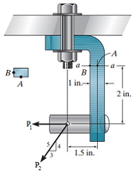
The joint is subjected to the force system shown in the figure below (Figure 1) where P1 = 200 lb and P2 = 560 lb. The member has a rectangular cross-sectional area of width 0.5 in. and thickness 1 in.
1) Part A: Determine the normal stress at point A.
2) Part B: Determine the normal stress at point B.
3) Part C: Determine the shear stress at point A.
4) Part D: Determine the shear stress at point B.

Transcribed Image Text:-A
I a
B
B
1 in.-
2 in.
P-
1.5 in."
P.
Expert Solution
This question has been solved!
Explore an expertly crafted, step-by-step solution for a thorough understanding of key concepts.
This is a popular solution
Trending nowThis is a popular solution!
Step by stepSolved in 2 steps with 2 images

Knowledge Booster
Learn more about
Need a deep-dive on the concept behind this application? Look no further. Learn more about this topic, mechanical-engineering and related others by exploring similar questions and additional content below.Similar questions
- The rectangular bar will be fabricated with an inclined glued joint at the mid-section as shown in the figure below. Assume that the ultimate stresses for the glue are 8 MPa in the tension and 4 MPa in shear. The factor of safety for the members is at least 2. a) b) w mm B d= Determine the optimum angle for the joint 0 = Ꮎ degree Load Determine the depth, d, for the allowable 35 kN loading and the width of 60mm mm Submit part Unanswered Submit part Unansweredarrow_forwardProblem 2. A material element in plane stress is subjected to stresses: Ox = -5000 psi Oy Txy = -3000 psi - 2000 psi а) Using Mohr's Circle, determine the stresses on an element oriented at an angle 0 = 60° counterclockwise from the x axis. b) Show these stresses on a sketch of an element oriented at the angle 0.arrow_forwardThe plate has a thickness of 20 mm and the force P = 3 kN acts along the centerline of this thickness such that d = 150 mm. A) Determine the normal stress at the bottom edge of the plate Enter negative value in the case of compression and positive value in the case of tension. B)Determine the normal stress at the top edge of the plate. Enter negative value in the case of compression and positive value in the case of tension. C)Specify the location of the neutral axis measured from the bottom edge of the plate.arrow_forward
- The beam is supported by a pin at B and a short link AC. All pins are in double shear as shown in and each has a diameter of 40 mm assume P1=98 kN and P2= 49 kN. A) Determine the average shear stress developed in the pin at A B) Determine the average shear stress developed in the pin at B C) Determine the average shear stress developed in the pin at Carrow_forward3. Four pulleys are attached to the 50-mm-diameter aluminum shaft. If torques are applied to the pulleys as shown in the figure, determine the maximum shear stress in each segment and the angle of rotation of pulley D relative to pulley A. Use G = 28 GPa for aluminum. a. Tab= b. Tbc= C. Tbc= ad= 1100 N·m 800 N·m D C 900 N·m 600 N m B A 2 m3 m2 marrow_forwardProblem 1: The lap joint shown in the figure is fastened by nine 20mm diameter rivets. Each plate has a thickness of 25mm and width of 250mm. Assuming that P = 50kN. a) Determine the shearing stress in each rivet b) Determine the bearing stress in each plate c) Determine the maximum average tensile stress in the most stress part of each plate.arrow_forward
- The yoke and rod connection assembly shown in the figure below is subjected to a tensile force of 5 kN. I Determine the tensile stress in each rod. Determine the shear stress in pin A between the members. If each rod is 600 mm long, determine the overall extension of the assembly. Ignore any stretch in the joint. 40 mm 5 kN. 30 mm 25 mm 5 kNarrow_forward- once answered Correctly will UPVOTE!!arrow_forward
arrow_back_ios
arrow_forward_ios
Recommended textbooks for you
 Elements Of ElectromagneticsMechanical EngineeringISBN:9780190698614Author:Sadiku, Matthew N. O.Publisher:Oxford University Press
 Mechanics of Materials (10th Edition)Mechanical EngineeringISBN:9780134319650Author:Russell C. HibbelerPublisher:PEARSON
 Thermodynamics: An Engineering ApproachMechanical EngineeringISBN:9781259822674Author:Yunus A. Cengel Dr., Michael A. BolesPublisher:McGraw-Hill Education
 Control Systems EngineeringMechanical EngineeringISBN:9781118170519Author:Norman S. NisePublisher:WILEY
 Mechanics of Materials (MindTap Course List)Mechanical EngineeringISBN:9781337093347Author:Barry J. Goodno, James M. GerePublisher:Cengage Learning
 Engineering Mechanics: StaticsMechanical EngineeringISBN:9781118807330Author:James L. Meriam, L. G. Kraige, J. N. BoltonPublisher:WILEY

Elements Of Electromagnetics
Mechanical Engineering
ISBN:9780190698614
Author:Sadiku, Matthew N. O.
Publisher:Oxford University Press

Mechanics of Materials (10th Edition)
Mechanical Engineering
ISBN:9780134319650
Author:Russell C. Hibbeler
Publisher:PEARSON

Thermodynamics: An Engineering Approach
Mechanical Engineering
ISBN:9781259822674
Author:Yunus A. Cengel Dr., Michael A. Boles
Publisher:McGraw-Hill Education

Control Systems Engineering
Mechanical Engineering
ISBN:9781118170519
Author:Norman S. Nise
Publisher:WILEY

Mechanics of Materials (MindTap Course List)
Mechanical Engineering
ISBN:9781337093347
Author:Barry J. Goodno, James M. Gere
Publisher:Cengage Learning

Engineering Mechanics: Statics
Mechanical Engineering
ISBN:9781118807330
Author:James L. Meriam, L. G. Kraige, J. N. Bolton
Publisher:WILEY