Elements Of Electromagnetics
7th Edition
ISBN: 9780190698614
Author: Sadiku, Matthew N. O.
Publisher: Oxford University Press
expand_more
expand_more
format_list_bulleted
Concept explainers
Question
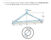
From the system shown in the figure, obtain the forces and the average axial stress on each bar AB, AC and BC. Use the transversal area shown below.

Transcribed Image Text:2. From the system shown in the figure, obtain the forces and the average axial stress
on each bar AB, AC and BC. Use the transversal area shown below.
20°
800 N
0.4 m
B
0.7 m-
- 0.7 m-
0.5 in
1 in
Expert Solution
This question has been solved!
Explore an expertly crafted, step-by-step solution for a thorough understanding of key concepts.
Step by stepSolved in 2 steps with 3 images

Knowledge Booster
Learn more about
Need a deep-dive on the concept behind this application? Look no further. Learn more about this topic, mechanical-engineering and related others by exploring similar questions and additional content below.Similar questions
- A single-piece bicycle crank is shown below under the following load: the rider pedals forward with a vertical force Fp = 500 N on the left pedal and no force on the right pedal. The chain exerts a force Fc on the chainring. The spindle is a solid cylinder with a diameter d = 16 mm. 1. Find the maximum normal stress and shear stress at cross-section y-y in image. Indicate the locations on the given cross section view where they act.arrow_forwardThere are forces acting in the Z and Y directions 1000N and 1500N please post your own correct answer everyone keeps copy and pasting an incorrect answer that neglects the stress acting in the y axisarrow_forwardFind the tensile stress in MPa in member AB shown in the figure All connection bars have a square cross section and the bar width is 15 mm. Points A, B and C are pin connections. Square 15 mm side 6m 3.5m C. D. 20KNarrow_forward
- The block of weight W in the figure below hangs from the pin at A. The bars AB and AC are pinned to the support at B and C. The areas are 800 mm2 for AB and 400 mm2 for AC. Neglecting the weight of the bars, determine the maximum safe value of W if the stress in AB is limited to 110 MPa and the in AC to 120 MPa.arrow_forwardFill in the blanks. Draw and label the Mohr’s circle. For sigma-yp = 30 kSf. does this fail? Find the stresses on the plane shown. Find the plane on which sigma-1 acts relative to the horizontal. Draw them on the figure. Draw the Tresca plot.arrow_forwardExplanation required, Don't directly paste the solution from other site⚠️arrow_forward
arrow_back_ios
SEE MORE QUESTIONS
arrow_forward_ios
Recommended textbooks for you
 Elements Of ElectromagneticsMechanical EngineeringISBN:9780190698614Author:Sadiku, Matthew N. O.Publisher:Oxford University Press
 Mechanics of Materials (10th Edition)Mechanical EngineeringISBN:9780134319650Author:Russell C. HibbelerPublisher:PEARSON
 Thermodynamics: An Engineering ApproachMechanical EngineeringISBN:9781259822674Author:Yunus A. Cengel Dr., Michael A. BolesPublisher:McGraw-Hill Education
 Control Systems EngineeringMechanical EngineeringISBN:9781118170519Author:Norman S. NisePublisher:WILEY
 Mechanics of Materials (MindTap Course List)Mechanical EngineeringISBN:9781337093347Author:Barry J. Goodno, James M. GerePublisher:Cengage Learning
 Engineering Mechanics: StaticsMechanical EngineeringISBN:9781118807330Author:James L. Meriam, L. G. Kraige, J. N. BoltonPublisher:WILEY

Elements Of Electromagnetics
Mechanical Engineering
ISBN:9780190698614
Author:Sadiku, Matthew N. O.
Publisher:Oxford University Press

Mechanics of Materials (10th Edition)
Mechanical Engineering
ISBN:9780134319650
Author:Russell C. Hibbeler
Publisher:PEARSON

Thermodynamics: An Engineering Approach
Mechanical Engineering
ISBN:9781259822674
Author:Yunus A. Cengel Dr., Michael A. Boles
Publisher:McGraw-Hill Education

Control Systems Engineering
Mechanical Engineering
ISBN:9781118170519
Author:Norman S. Nise
Publisher:WILEY

Mechanics of Materials (MindTap Course List)
Mechanical Engineering
ISBN:9781337093347
Author:Barry J. Goodno, James M. Gere
Publisher:Cengage Learning

Engineering Mechanics: Statics
Mechanical Engineering
ISBN:9781118807330
Author:James L. Meriam, L. G. Kraige, J. N. Bolton
Publisher:WILEY