
Structural Analysis
6th Edition
ISBN: 9781337630931
Author: KASSIMALI, Aslam.
Publisher: Cengage,
expand_more
expand_more
format_list_bulleted
Related questions
Concept explainers
Question
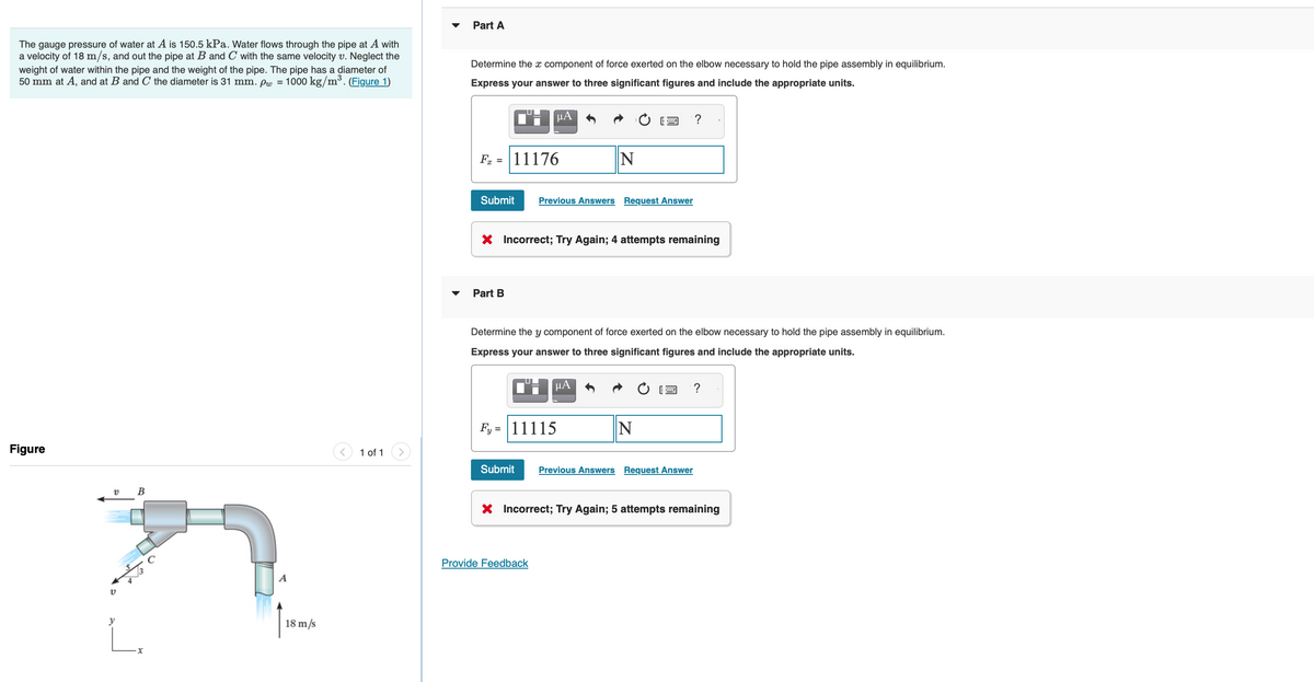

Transcribed Image Text:The gauge pressure of water at A is 150.5 kPa. Water flows through the pipe at A with
a velocity of 18 m/s, and out the pipe at B and C with the same velocity v. Neglect the
weight of water within the pipe and the weight of the pipe. The pipe has a diameter of
50 mm at A, and at B and C the diameter is 31 mm. pw = 1000 kg/m³. (Figure 1)
Figure
v B
v
y
L.
18 m/s
1 of 1
Part A
Determine the x component of force exerted on the elbow necessary to hold the pipe assembly in equilibrium.
Express your answer to three significant figures and include the appropriate units.
F = 11176
Submit
μА
Part B
Previous Answers Request Answer
X Incorrect; Try Again; 4 attempts remaining
N
Determine the y component of force exerted on the elbow necessary to hold the pipe assembly in equilibrium.
Express your answer to three significant figures and include the appropriate units.
μA
Fy=11115
Provide Feedback
?
N
Submit Previous Answers Request Answer
?
X Incorrect; Try Again; 5 attempts remaining
Expert Solution
This question has been solved!
Explore an expertly crafted, step-by-step solution for a thorough understanding of key concepts.

This is a popular solution

Trending nowThis is a popular solution!

Step by stepSolved in 5 steps with 6 images

Knowledge Booster


Learn more about
Need a deep-dive on the concept behind this application? Look no further. Learn more about this topic, civil-engineering and related others by exploring similar questions and additional content below.Similar questions
- Two pipes A and B are connected in parallel between two points M and N as shown in figure. Pipe A is 80 mm diameter, 900 m long and its friction factor is 0.015. Pipe B is of 100 mm diameter, 700 m long and its friction factor is 0.018. A total discharge of 0.030 m³/s is entering the parallel pipes through the division at M. Calculate the discharge in the two pipes A and B. M = 0.015 A fA 80 mm dia, 900 m 100 mm dia, 700 m B fB = = 0.018 Narrow_forwardWater flows through the branching pipe shown in the figure below. The flowrate at section (1) is Q₁ = 1.1 m³/s, and the velocity at section (2) is V₂ = 17 m/s. A₁ = 0.1 m² P1 = 300 kPa 21 = 0 P3 = -147.2 A3 = 0.035 m² Z3 = 10 m (1) (2) If viscous effects are negligible, determine the pressure at section (2) and the pressure at section (3). P2 = i 315.3 kPa kPa (3) A₂ = 0.03 m² 22 = 0arrow_forwardConsider the tank shown in (Eigure 1). Take po = 900 kg/m³, Pu=1000 kg/m³, and pHg = 13 550 kg/m³. 0.6 m 0.8 m 100 mm h 1 of 1 > P Part A Determine the level of water in the tube if the depths of ol and water in the tank are 0.6 m and 0.8 m. respectively, and the height of mercury in the tube is h=0.075 m A Express your answer to three significant figures and include the appropriate units. PA h = 240 Submit + Provide Feedback → OF ? mm Previous Answers Request Answen X Incorrect; Try Again; 4 attempts remaining Next > 1231 AM 0arrow_forward
- Q- In a pond at a depth of 5m air bubble is formed of diameter 0.8mm. Calculate gauge pressure inside air bubble. Assume surface tension = 0.075N/m.arrow_forwardConsider the pressurized horizontal pipe network consisting of three pipes arranged in series. The characteristics of each pipe are summarized in the table. The flow of water at Node A is Q = 5 cfs and the pressure head at Node A is yA = 200 feet. The temperature of the water is 60° F. a) Determine the friction head loss hfric in feet in Pipe 1. b) Determine the friction head loss hfric in feet in Pipe 2. c) Determine the friction head loss hfric in feet in Pipe 3. d) Determine the pressure head ys in feet at Node B. e) Determine the pressure head yc in feet at Node C. f) Determine the pressure head yo in feet at Node D. Flow Friction Pressure Diameter Length Friction (feet) (cfs) head Нead Pipe (inches) factor f Kpipe loss (feet) Node (feet) 1 16 500 0.011 5 A 200 2 12 1000 0.013 B 3 10 750 0.015 D Node Node Node Node A в D 5 cfs 5 cfs Pipe 1 Pipe 2 Pipe 3arrow_forward
arrow_back_ios
arrow_forward_ios
Recommended textbooks for you
 Structural Analysis (10th Edition)Civil EngineeringISBN:9780134610672Author:Russell C. HibbelerPublisher:PEARSON
 Principles of Foundation Engineering (MindTap Cou...Civil EngineeringISBN:9781337705028Author:Braja M. Das, Nagaratnam SivakuganPublisher:Cengage Learning
 Fundamentals of Structural AnalysisCivil EngineeringISBN:9780073398006Author:Kenneth M. Leet Emeritus, Chia-Ming Uang, Joel LanningPublisher:McGraw-Hill Education
 Traffic and Highway EngineeringCivil EngineeringISBN:9781305156241Author:Garber, Nicholas J.Publisher:Cengage Learning
Structural Analysis (10th Edition)
Civil Engineering
ISBN:9780134610672
Author:Russell C. Hibbeler
Publisher:PEARSON
Principles of Foundation Engineering (MindTap Cou...
Civil Engineering
ISBN:9781337705028
Author:Braja M. Das, Nagaratnam Sivakugan
Publisher:Cengage Learning
Fundamentals of Structural Analysis
Civil Engineering
ISBN:9780073398006
Author:Kenneth M. Leet Emeritus, Chia-Ming Uang, Joel Lanning
Publisher:McGraw-Hill Education
Traffic and Highway Engineering
Civil Engineering
ISBN:9781305156241
Author:Garber, Nicholas J.
Publisher:Cengage Learning