
Elements Of Electromagnetics
7th Edition
ISBN: 9780190698614
Author: Sadiku, Matthew N. O.
Publisher: Oxford University Press
expand_more
expand_more
format_list_bulleted
Related questions
Question
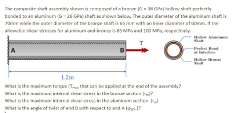

Transcribed Image Text:The composite shaft assembly shown is composed of a bronze (G = 38 GPa) hollow shaft perfectly
bonded to an aluminum (G = 26 GPa) shaft as shown below. The outer diameter of the aluminum shaft is
70mm while the outer diameter of the bronze shaft is 65 mm with an inner diameter of 60mm. If the
allowable shear stresses for aluminum and bronze is 85 MPa and 100 MPa, respectively.
Hollow Aluminm
Shaf
Perfect Bond
at Interface
Holow Brone
Shaft
1.2m
What is the maximum torque (T that can be applied at the end of the assembly?
What is the maximum internal shear stress in the bronze section (T)?
What is the maximum internal shear stress in the aluminum section (T)
What is the angle of twist of end B with respect to end A (Pau }?
Expert Solution
This question has been solved!
Explore an expertly crafted, step-by-step solution for a thorough understanding of key concepts.

This is a popular solution

Trending nowThis is a popular solution!

Step by stepSolved in 4 steps with 5 images

Knowledge Booster

Similar questions
- The shaft consists of a titanium alloy tube AB and a solid stainless steel shaft BC. Tube AB has a length of L = 40 in., an outside diameter of dị = 1.75 in., and a wall thickness of tn = 0.125 in. Shaft BC has a length of L2 = 50 in. and a diameter of d2 = 1.25 in. Use G = 6,500 ksi for the tube AB, and G = 11,000 ksi for the shaft BC. The torque Te = 290 lb-ft acts at pulley C in the direction shown. TC L2 B 1. Determine the maximum shear stress in the shaft BC. A) 7.56 ksi B) 18.1 ksi C) 10.5 ksi D) 9.07 ksi E) None of the Abovearrow_forward4) Ball bearings support the rotating axle shown below at points A and D. The rotating axle is loaded by a stationary (non-rotating) force of F = 6.8 kN. In the drawing below, all dimensions are in mm, and all geometry changes (steps in the diameter shaft) have a fillet radius of 3 mm. The axle is machined from AISI cold-drawn steel with an ultimate strength of S_u = 690 MPa and a yield strength of S_y= 580 MPa. Calculate the safety factor at the 6.8 kN load and points B and C, which experience moderate bending moments with a geometric feature that causes a stress concentration. Determine the number of cycles to failure of this part. 30 -10 -250 32 B 6.8 KN 75 -38 100- с 125 10 35 D 30arrow_forward4. What length of a square key is required for a 4-in diameter shaft transmitting 1000 hp at 1000 RPM? The allowable shear and compressive stresses in the key are 15 ksi and 30 ksi, respectively.arrow_forward
- A 28mm diameter steel shaft AB is built into a rigid wall at A and supported by a smooth bearing at B. The lever BC is welded to the end of the shaft. Load P 360 newton is applied as shown in the figure below. Determine the maximum shear stress and the angle of twist if the distance from A to B is 3 meters and the distance from B to C is .3 metersarrow_forwardPlease help with the stress, mohir circle, etc. Thank youarrow_forwardPlease help. This problem involves torsional stress and strain. Thank you.arrow_forward
- Please help. This problem involves torsional stress and strain. Thank you.arrow_forwardThe shaft in Figure below consists of a 3-in. -diameter aluminum segment that is rigidly joined to a 2-in. -diameter steel segment. The ends of the shaft are attached to rigid supports, Calculate the maximum shear stress developed in each segment when the torque T= 10 kip.in is applied. Use G = 4×10⁶ psi for aluminum and G = 12×106 psi for steel. Aluminum 3-in. diameter 6 ft T Steel 2-in. diameter 3 ftarrow_forwardA round shaft of diamater D = 65 mm with a groove cut into it where the diameter decreases to d = 50 mm. The radius of the fillet at the groove is r = %3D 2.5 mm. If the internal torsional moment at a critical cross-section in the groove is 400 N.m, calculate the maximum torsional shear stress at the groove. Round-up your answer to the nearest MPa. Max torsional shear stress MPaarrow_forward
arrow_back_ios
arrow_forward_ios
Recommended textbooks for you
- Elements Of ElectromagneticsMechanical EngineeringISBN:9780190698614Author:Sadiku, Matthew N. O.Publisher:Oxford University Press
 Mechanics of Materials (10th Edition)Mechanical EngineeringISBN:9780134319650Author:Russell C. HibbelerPublisher:PEARSON
 Thermodynamics: An Engineering ApproachMechanical EngineeringISBN:9781259822674Author:Yunus A. Cengel Dr., Michael A. BolesPublisher:McGraw-Hill Education
  Control Systems EngineeringMechanical EngineeringISBN:9781118170519Author:Norman S. NisePublisher:WILEY
 Mechanics of Materials (MindTap Course List)Mechanical EngineeringISBN:9781337093347Author:Barry J. Goodno, James M. GerePublisher:Cengage Learning
 Engineering Mechanics: StaticsMechanical EngineeringISBN:9781118807330Author:James L. Meriam, L. G. Kraige, J. N. BoltonPublisher:WILEY
Elements Of Electromagnetics
Mechanical Engineering
ISBN:9780190698614
Author:Sadiku, Matthew N. O.
Publisher:Oxford University Press
Mechanics of Materials (10th Edition)
Mechanical Engineering
ISBN:9780134319650
Author:Russell C. Hibbeler
Publisher:PEARSON
Thermodynamics: An Engineering Approach
Mechanical Engineering
ISBN:9781259822674
Author:Yunus A. Cengel Dr., Michael A. Boles
Publisher:McGraw-Hill Education
Control Systems Engineering
Mechanical Engineering
ISBN:9781118170519
Author:Norman S. Nise
Publisher:WILEY
Mechanics of Materials (MindTap Course List)
Mechanical Engineering
ISBN:9781337093347
Author:Barry J. Goodno, James M. Gere
Publisher:Cengage Learning
Engineering Mechanics: Statics
Mechanical Engineering
ISBN:9781118807330
Author:James L. Meriam, L. G. Kraige, J. N. Bolton
Publisher:WILEY