Question

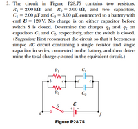
Transcribed Image Text:3. The circuit in Figure P28.75 contains two resistors,
R1 = 2.00 k2 and R2 = 3.00 kN, and two capacitors,
C = 2.00 µF and C2 = 3.00 µF, connected to a battery with
emf ɛ = 120 V. No charge is on either capacitor before
switch S is closed. Determine the charges q1 and q2 on
capacitors C1 and C2, respectively, after the switch is closed.
(Suggestion: First reconstruct the circuit so that it becomes a
simple RC circuit containing a single resistor and single
capacitor in series, connected to the battery, and then deter-
mine the total charge qstored in the equivalent circuit.)
%3D
%3D
%3D
R1
R2
C2
S
Figure P28.75
Expert Solution
This question has been solved!
Explore an expertly crafted, step-by-step solution for a thorough understanding of key concepts.
This is a popular solution
Trending nowThis is a popular solution!
Step by stepSolved in 6 steps

Knowledge Booster
Similar questions
- A heart pacemaker fires exactly 71 times a minute. Each time it fires, a 19.0 nF capacitor is charged by a battery in series with a resistor to 0.582 of its full voltage. What is the value of the resistance R? R =arrow_forwardYou are given the below circuit to analyze and told that the circuit has been complete for a long time. What is the charge of capacitor C1? In the circuit, Rд=41 £2, RB=621 £2, Rc=110 £2, С₁=54 μF, C₂=22 μF, Vc3-6 V and V1=38.3 V. The charge on C₁ = V₁ ww RA w RB C1 C₂ C3 M Rcarrow_forwardA 15 microFarad capacitor is in a circuit with a 4.0 V battery. Electrons will move after the switch is closed. What is the energy stored in the capacitor after the switch is closed long enough time?arrow_forward
- E2 R1 R2 2. Find the charge on the capacitor after the switch has been left open for some time, then closed for some period of time. We can assume that C = 2 µF, with batteries of values E1 R2 = 0.25 N. 2V and E2 =1V, and resistor values R1 = 0.5 N and Sarrow_forwardA parallel combination of a 1.31 µF capacitor and a 2.73 pF capacitor is connected in series to a 4.53 µF capacitor. This three-capacitor combination is connected to a 19.5 V battery. Determine the charge on each capacitor. charge of 4.53 uF capacitor: 0.00003895 C charge of 1.31 µF capacitor: 0.0000096 charge of 2.73 uF capacitor: 0.0000242 Carrow_forward+ 100 V A B C₁ 10 uF C₂ C₂ 20.5 UF 37.5 uf T Initially the switch in the circuit depicted above is in position A and capacitors C₂ and C3 are uncharged. Then the switch is flipped to position B. What are the charges on and the potential difference across each of the three capacitors? Note1: The capacitor values in the Figure above are all in µF.arrow_forward
- = The circuit in the figure below contains two resistors, R₁ 5.00k and R₂ 6.00k, and two capacitors, C₁ = 5.00uF and C₂ = 6.00uF, connected to a battery with emf E = 110V. If no charges exist on the capacitors before switch S is closed, determine the charge 9₁ on capacitor C₁ 1.00ms after the switch is closed. R₁ C₁ de b с www R₂ S afor C₂ E Determine the charge 92 on capacitor C₂ 1.00ms after the switch is closed.arrow_forwardTwo capacitors C₁ = 40 µF and C₂ = 20 µF and two resistors R₁ = 80 ≤ and R₂ = 55 ≤ are connected to a 3-V battery as shown in the figure below. What is the potential difference between points a and b? R₁ R₂ а mina ^^^ HI C₁ b V HE €₂ The potential difference, V₁-Vb = Units Select an answer ✓arrow_forwardTwo capacitors of capacitance C₁ = 500 nF and C₂ = 1.5 μF are connected in series across a cell with emf V = 8V. What is the energy stored on C₁?arrow_forward
arrow_back_ios
arrow_forward_ios