Introductory Circuit Analysis (13th Edition)
13th Edition
ISBN: 9780133923605
Author: Robert L. Boylestad
Publisher: PEARSON
expand_more
expand_more
format_list_bulleted
Question
Please answer in typing format

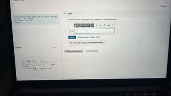
Transcribed Image Text:The b parameters of the amplifier in the circuit shown in figure are
b11=23; b12 = 1000;
b21-1.24 S; b22=-36.
(Figure 1)
Part A
Find the ratio of the output power to that supplied by the ideal voltage source.
10 ΑΣΦ. 11 vec
?
Figure
2002
Submit
Previous Answers Request Answer
Incorrect; Try Again; 5 attempts remaining
1 of 1
< Return to Assignment
Provide Feedback
120/0 V V Amplifier
(rms)
100
Medtick Pro
Constants
Expert Solution
This question has been solved!
Explore an expertly crafted, step-by-step solution for a thorough understanding of key concepts.
Step by stepSolved in 2 steps

Knowledge Booster
Similar questions
- 4. A current measuring operational amplifier is made by bridging a resistor across the inverting terminal (pin 2) and the output terminal (pin 6). The noninverting terminal is grounded. a. Draw a sketch of the current measuring circuit. Determine an appropriate resistor for converting a current of 1.0 picoamperes (1.0 × 10-¹2 A) to a voltage of 0.010 V. (The math for this question is very easy, don't overthink this question. b. There are a few reasons that circuit you drew in part a will not be effective. First, you will have a difficult time finding a resistance with the required resistance value. Second, the input terminals do not have infinite resistance value. In fact, for an inexpensive 741 op-amp, the input terminal resistance may only be a few MOhms, which is far less than the resistance your calculated for the feedback resistor. This means that more current will be drawn into the op-amp than will go around it. Finally, the op-amp may have a bias current that is larger than the…arrow_forwardPlease in typing format please ASAP for Thanks ?arrow_forwardQ-1-a) From the circuit in the Figure-1, determine the DC-bias operation Parameters: (iv) VBE (v) VB (vi) Vc (vii) VCE (viii) Ve (Figure-1) Rg= 380kN,Rc= 1kN B = 100, VBB = Vcc=12V RB ww. + Vc CC I, BE BB Q-1-b) Describe briefly the input / output characteristics and application of Common Emitter BJT Configurationarrow_forward
- The transistor parameters for the circuit in Figure are B1 =B2 = 100, VBE1(on) = VBE2(on) = 0.7 V, and VA1 = VA2 %3D =00.Find the small signal voltage gain Av = vo/vs. (Note that VT=0.026 V) %3D Vcc=9 V Rib Q2 1 ko -R. 20 V 100 Q -14.76 O 0.899 -55.3 ww wwarrow_forwardA differential op-amp circuit as shown below is used to implement a given linear voltage measuring functionV = f(V,). ouf Provide answers to questions 19 – 22. ww V. V; W R out R2 Groundarrow_forwardplease answer all thanks !arrow_forward
- Anything AND'ed with its complement will give an output of a.0 b.1 c.Could be 1 or 0 d.This is not a situation that could ever occurarrow_forwardplease show step by step working for this question with circuit diagrams if possible so I can understand the circuit better thank you.(please handwrite the solutions)arrow_forwardQ-1-a) From the circuit in the Figure-1, determine the DC-bias operation Parameters: (i) IB (ii) Ic (iii) le (iv) VBE (v) VB (vi) Vc (vii) VCE (viii) Ve (Figure-1) Rg= 380kN,Rc= 1kQ B = 100, VBB = Vcc=12V RB ww. + BE BB Q-1-b) Describe briefly the input / output characteristics and application of Common Emitter BJT Configuration wwarrow_forward
- Please answer ASAP for like this please It's urgent please I will like it definitely please..arrow_forwardPlease show me the derivation of equation 1-4 with a reasonable assumptionarrow_forwardQuestion 4 Consider a BJT amplifier cireuit in Figure 4. Assume that BDC = 110, Bac- 100 remains constant during the operating conditions and Ri =2 k2. Vec +30V Rc 3 kn C, Vout R 20k 10uF Vin o 10 uF R 2kn R: Skn RE 1 ka 10 uF Figure 4 (a) Draw the de and ac equivalent cireuit for the BJT amplifier circuit. (b) Calculate the following values for the amplifier: Va, Vr, Ir, r'e, Riche Ruun, and A. (e) Evaluate the effect to the voltage gain if the bypass capacitor C2 and load resistor R, is removed from the amplifier. (d) Modify the circuit in Figure 4 to minimize the effect of r'e without reducing the voltage gain to its minimum value.arrow_forward
arrow_back_ios
SEE MORE QUESTIONS
arrow_forward_ios
Recommended textbooks for you
 Introductory Circuit Analysis (13th Edition)Electrical EngineeringISBN:9780133923605Author:Robert L. BoylestadPublisher:PEARSON
 Delmar's Standard Textbook Of ElectricityElectrical EngineeringISBN:9781337900348Author:Stephen L. HermanPublisher:Cengage Learning
 Programmable Logic ControllersElectrical EngineeringISBN:9780073373843Author:Frank D. PetruzellaPublisher:McGraw-Hill Education
 Fundamentals of Electric CircuitsElectrical EngineeringISBN:9780078028229Author:Charles K Alexander, Matthew SadikuPublisher:McGraw-Hill Education
 Electric Circuits. (11th Edition)Electrical EngineeringISBN:9780134746968Author:James W. Nilsson, Susan RiedelPublisher:PEARSON
 Engineering ElectromagneticsElectrical EngineeringISBN:9780078028151Author:Hayt, William H. (william Hart), Jr, BUCK, John A.Publisher:Mcgraw-hill Education,

Introductory Circuit Analysis (13th Edition)
Electrical Engineering
ISBN:9780133923605
Author:Robert L. Boylestad
Publisher:PEARSON

Delmar's Standard Textbook Of Electricity
Electrical Engineering
ISBN:9781337900348
Author:Stephen L. Herman
Publisher:Cengage Learning

Programmable Logic Controllers
Electrical Engineering
ISBN:9780073373843
Author:Frank D. Petruzella
Publisher:McGraw-Hill Education

Fundamentals of Electric Circuits
Electrical Engineering
ISBN:9780078028229
Author:Charles K Alexander, Matthew Sadiku
Publisher:McGraw-Hill Education

Electric Circuits. (11th Edition)
Electrical Engineering
ISBN:9780134746968
Author:James W. Nilsson, Susan Riedel
Publisher:PEARSON

Engineering Electromagnetics
Electrical Engineering
ISBN:9780078028151
Author:Hayt, William H. (william Hart), Jr, BUCK, John A.
Publisher:Mcgraw-hill Education,