Introductory Circuit Analysis (13th Edition)
13th Edition
ISBN: 9780133923605
Author: Robert L. Boylestad
Publisher: PEARSON
expand_more
expand_more
format_list_bulleted
Question

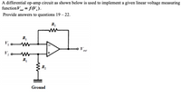
Transcribed Image Text:A differential op-amp circuit as shown below is used to implement a given linear voltage measuring
functionV = f(V,).
ouf
Provide answers to questions 19 – 22.
ww
V.
V; W
R
out
R2
Ground

Transcribed Image Text:21. If the specified linear measuring function is Vout = 1.4V% – 4.35 V, the input voltage
values of the differential op-amp circuit must be
(a) V, = 3.11 V and V2 = V
(c) V1 = -3.11 V and V2 = V
(b) V, = V and V½ = – 4.35 V
(d) V, = - 4.35V and V2 = V
Expert Solution
This question has been solved!
Explore an expertly crafted, step-by-step solution for a thorough understanding of key concepts.
Step by stepSolved in 2 steps with 2 images

Knowledge Booster
Learn more about
Need a deep-dive on the concept behind this application? Look no further. Learn more about this topic, electrical-engineering and related others by exploring similar questions and additional content below.Similar questions
- In the op amp model above, open-loop gain is 105 and Vcc=12V. Suppose the inverting-input voltage is vn=44μV and the noninverting input voltage vp=284μV. What is the op-amp’s output voltage vo (in volts)?arrow_forward2)For the following circuit, assuming the Op-Amp is ideal, fill in the table for the missing values when vi = 2V, 12 10 k [mA] [mA] [mA] [mA] ...... I kn lo I2 ...... IL Io o vo vi ........arrow_forwardFor the given op-amp circuit, determine: (a) iout/iin2, (b) iin2/iin, (c) iin/Is, and (d) iout/Is.arrow_forward
- Discuss what a difference amp is, give equations and details, what is a single-ended and differential signal, what is a 4-20 mA signal, what is common-mode noise and why is a difference amp used?arrow_forwardA certain op-amp has two internal amplifier stages with the following gains and critical frequencies; Av1 = 50 dB, Av2 = 25 dB, fc1 = 1500 Hz, and fc2 = 3000 Hz. Determine the open loop midrange gain in decibels and total phase lag when f = fc1....arrow_forward(a) An operational amplifier shown in Figure 1. Sketch the real circuit model of the amplifier. As a real op-amp it has the following specifications: Input resistance Output resistance Open-loop gain Rin=1MQ Ro=2002 Ao=100,000 190KQ Figure. 1arrow_forward
- a) For an opamp, the input bias current Ib =60uA and the input offset current lio= 10uA Find the input base currents and In b) Design an opamp circuit with the following output: Vo = - Vin/4 + 2 For the circuit given below Given :Vin-0.2V, Vsat= 12V D Identify (name) the circuit (stage 1 and 2) O Find the output voltage Vo and the current through the load 4ka 0 Find Vo if the resistor 2kn opens 10 k Stage Stage 2 Vo Vinarrow_forwardThe midrange open-loop gain, "Aol(mid)" of a certain op-amp is 80,000. If the open-loop critical frequency is 1 kHz, what is the open-loop gain, "Aol" at each of the following frequencies? (a)100 Hz (b) 1 MHzarrow_forward3R The op-amp will only slightly amplify signals: a.when the supply voltages are less than +/- 25V b.that are common on both the inputs c.that are different on both the inputs d.when the supply voltages are more than +/- 25Varrow_forward
- Assuming an ideal· op-amp's saturation voltage- UsSAT = +15V. For the- circuit in Figure · if u = 3V, the output voltage of op-amp is (404) i 10arrow_forward+Vcc Vin VI Vo Vref VN -Vcc Ry RxL Figure Q.A2(e). Inverting Schmitt-trigger circuit. (ii) The operational-amplifier (op-amp) of the inverting Schmitt-trigger in Figure Q.A2(e) has saturation voltages of +Vsat = +11 V and -Vsat = -11 V. The voltage divider circuit has the relationship of Rx = 2RY with the value of RY being 100 kn. Using the relationships derived above: (a) Calculate the values of the upper threshold point (UTP or Vi*), lower threshold point (LTP or Vr). (b) Now, sketch the input-output characteristic of the inverting Schmitt- trigger. Clearly label axes, the threshold voltages and the saturation voltages in your sketch.arrow_forwardAnswer the following questions a) What assumption do we make for an ideal op - amp? b) Explain what slew rate is why it is important characteristic for an op amp.arrow_forward
arrow_back_ios
arrow_forward_ios
Recommended textbooks for you
 Introductory Circuit Analysis (13th Edition)Electrical EngineeringISBN:9780133923605Author:Robert L. BoylestadPublisher:PEARSON
 Delmar's Standard Textbook Of ElectricityElectrical EngineeringISBN:9781337900348Author:Stephen L. HermanPublisher:Cengage Learning
 Programmable Logic ControllersElectrical EngineeringISBN:9780073373843Author:Frank D. PetruzellaPublisher:McGraw-Hill Education
 Fundamentals of Electric CircuitsElectrical EngineeringISBN:9780078028229Author:Charles K Alexander, Matthew SadikuPublisher:McGraw-Hill Education
 Electric Circuits. (11th Edition)Electrical EngineeringISBN:9780134746968Author:James W. Nilsson, Susan RiedelPublisher:PEARSON
 Engineering ElectromagneticsElectrical EngineeringISBN:9780078028151Author:Hayt, William H. (william Hart), Jr, BUCK, John A.Publisher:Mcgraw-hill Education,

Introductory Circuit Analysis (13th Edition)
Electrical Engineering
ISBN:9780133923605
Author:Robert L. Boylestad
Publisher:PEARSON

Delmar's Standard Textbook Of Electricity
Electrical Engineering
ISBN:9781337900348
Author:Stephen L. Herman
Publisher:Cengage Learning

Programmable Logic Controllers
Electrical Engineering
ISBN:9780073373843
Author:Frank D. Petruzella
Publisher:McGraw-Hill Education

Fundamentals of Electric Circuits
Electrical Engineering
ISBN:9780078028229
Author:Charles K Alexander, Matthew Sadiku
Publisher:McGraw-Hill Education

Electric Circuits. (11th Edition)
Electrical Engineering
ISBN:9780134746968
Author:James W. Nilsson, Susan Riedel
Publisher:PEARSON

Engineering Electromagnetics
Electrical Engineering
ISBN:9780078028151
Author:Hayt, William H. (william Hart), Jr, BUCK, John A.
Publisher:Mcgraw-hill Education,