EBK ELECTRICAL WIRING RESIDENTIAL
19th Edition
ISBN: 9781337516549
Author: Simmons
Publisher: CENGAGE LEARNING - CONSIGNMENT
expand_more
expand_more
format_list_bulleted
Concept explainers
Question

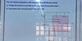
Transcribed Image Text:The 555 timer connected in the monostable multivibrator mode:
a) Design the circult to provide an output pulse 60 seconds wide?
b) Determine the recovery time? Take: B = 100
RA
www
Ca :V.(t)
V.
Ve
Discharge
Threshold
Trigg
Gnd
Control
Reset
555 cutput
V₂
Expert Solution
This question has been solved!
Explore an expertly crafted, step-by-step solution for a thorough understanding of key concepts.
Step by stepSolved in 4 steps with 2 images

Knowledge Booster
Learn more about
Need a deep-dive on the concept behind this application? Look no further. Learn more about this topic, electrical-engineering and related others by exploring similar questions and additional content below.Similar questions
- A 555 timer configured to run as an astable mode oscillator is shown in Figure 1. If the output is needed to have 30% duty cycle, i) Determine the required value of Rị if R2 = 7kN. ii) Determine the frequency of the output. iii) Draw the charging and discharging phase of capacitor Cext and its relation with the output waveform. ASsume Vcc = 12 V. +Vcc (4) |(8) R1 RESET Vcc (7) DISCH 555 D1 R2 (6) THRESH (3) OUT (2) TRIG (5) CONT GND :Cext 0.01 µF (1) 0.01µF Figure 1arrow_forwardPlease include detailsarrow_forwardhese blockS. c) Explain the difference between the modulator and demodulator blocks and explain the terms up-conversion and down-conversion.arrow_forward
- 4. The LM317 is an example of an IC A. three-terminal negative voltage regulator B. variable positive voltage regulator C. fixed positive voltage regulator D. switching regulator 5. Analog multiplexer called time-division multiplexer because of: A. It required fixed time period to operate. B. The signals are time overlapped throughout the output. C. The MOSFETS turning on and off half of the time. D. The input signals are time variants. 6. The basic difference between a series regulator and a shunt regulator is: A. the amount of current that can be handled B. the position of the control element C. the type of sample circuit D. the type of error detectorarrow_forwarda. What are DC Choppers? Explain what TRC (Time Ratio Control) is b. A Buck Converter is used with a 2mH inductor and a supply voltage of 15V. The load resistance is maintained at 1 Q. The switching frequency is 100 kHz. i. Determine the duty cycle needed for an output voltage of 5V. ii. Calculate the output supply voltage ripple. iii. What are the consequences of decreasing the load resistance by 50% (to 0.5 ohms)? c. Identify the class of converter in the figure and describe the principle of operation of such a converter. d. State a possible application of such a converter. e. Draw the output waveforms of the current and voltage and the gate pulses of the choppers. Indicate on the current waveform the region of operation of the choppers and diodes. CH₁ CH₂ AD₂ Chopper wwwroo E +← Voarrow_forwardc) A buck converter with constant frequency peak current mode control has Vs = 28V, V = 20V, L = 301uH, fs = 100 kHz. Find the ramp slop for the optimum compensation and the peak compensation voltage. %3Darrow_forward
- Describe Amplitude Modulator as one of an OTA applications the subject : Analogue Electronics II please wright clear and explean.arrow_forward8. Consider the DC motor with H-bridge PWM power amplifier that operates at frequency Fs = 1 kHz. Rated voltage of DC power supply is Udc = 24 V. Reference signal Uc = 0.5. Find the duration of the positive pulse in ms. a) 1 b) 0.5 c) 0.75 d) 0.25arrow_forwardSketch and explain the output for the circuit of given parameters. The generator signal is a sine wave with a 10V peak. The diode is germanium and has a forward resistance rf of 25 ohms. (Using Third Diode Approximation)arrow_forward
arrow_back_ios
SEE MORE QUESTIONS
arrow_forward_ios
Recommended textbooks for you
 EBK ELECTRICAL WIRING RESIDENTIALElectrical EngineeringISBN:9781337516549Author:SimmonsPublisher:CENGAGE LEARNING - CONSIGNMENT

EBK ELECTRICAL WIRING RESIDENTIAL
Electrical Engineering
ISBN:9781337516549
Author:Simmons
Publisher:CENGAGE LEARNING - CONSIGNMENT