
Introductory Circuit Analysis (13th Edition)
13th Edition
ISBN: 9780133923605
Author: Robert L. Boylestad
Publisher: PEARSON
expand_more
expand_more
format_list_bulleted
Related questions
Question
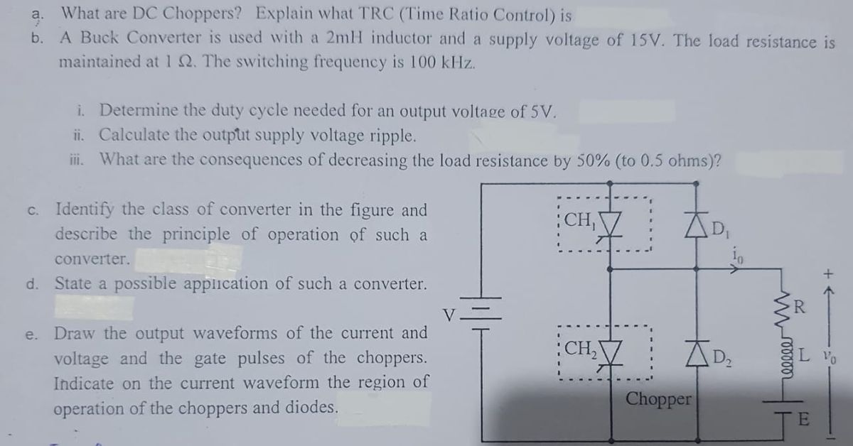

Transcribed Image Text:a. What are DC Choppers? Explain what TRC (Time Ratio Control) is
b. A Buck Converter is used with a 2mH inductor and a supply voltage of 15V. The load resistance is
maintained at 1 Q. The switching frequency is 100 kHz.
i. Determine the duty cycle needed for an output voltage of 5V.
ii. Calculate the output supply voltage ripple.
iii. What are the consequences of decreasing the load resistance by 50% (to 0.5 ohms)?
c. Identify the class of converter in the figure and
describe the principle of operation of such a
converter.
d. State a possible application of such a converter.
e. Draw the output waveforms of the current and
voltage and the gate pulses of the choppers.
Indicate on the current waveform the region of
operation of the choppers and diodes.
CH₁
CH₂
AD₂
Chopper
wwwroo
E
+←
Vo
Expert Solution
This question has been solved!
Explore an expertly crafted, step-by-step solution for a thorough understanding of key concepts.

Step by stepSolved in 2 steps

Knowledge Booster


Learn more about
Need a deep-dive on the concept behind this application? Look no further. Learn more about this topic, electrical-engineering and related others by exploring similar questions and additional content below.Similar questions
- Q6. A shunt motor rotating at 1500 rpm is fed by a 120 V source. The line current is 51 A and the shunt field resistance is 1202. If the armature resistance is 0.1 2, Determine: [6] (i) The current in the armature (ii) The counter emf (iii) The mechanical power developed by the motorarrow_forwardDerive the transfer function of Armature controlled DC shunt motorarrow_forwardQ2:A common actuator in control systems is the DC motor, determine the transfer function of the armature-controlled DC motor system described below. Represent the transfer function in terms of the input voltage (V) and the output angular velocity 0. Where T = Ki and e = Kė. Suter winding Angk Bearings R Bruss Armature P circuit Rotor Fixed fieldarrow_forward
arrow_back_ios
arrow_forward_ios
Recommended textbooks for you
- Introductory Circuit Analysis (13th Edition)Electrical EngineeringISBN:9780133923605Author:Robert L. BoylestadPublisher:PEARSON
 Delmar's Standard Textbook Of ElectricityElectrical EngineeringISBN:9781337900348Author:Stephen L. HermanPublisher:Cengage Learning
 Programmable Logic ControllersElectrical EngineeringISBN:9780073373843Author:Frank D. PetruzellaPublisher:McGraw-Hill Education
  Fundamentals of Electric CircuitsElectrical EngineeringISBN:9780078028229Author:Charles K Alexander, Matthew SadikuPublisher:McGraw-Hill Education
 Electric Circuits. (11th Edition)Electrical EngineeringISBN:9780134746968Author:James W. Nilsson, Susan RiedelPublisher:PEARSON
 Engineering ElectromagneticsElectrical EngineeringISBN:9780078028151Author:Hayt, William H. (william Hart), Jr, BUCK, John A.Publisher:Mcgraw-hill Education,
Introductory Circuit Analysis (13th Edition)
Electrical Engineering
ISBN:9780133923605
Author:Robert L. Boylestad
Publisher:PEARSON
Delmar's Standard Textbook Of Electricity
Electrical Engineering
ISBN:9781337900348
Author:Stephen L. Herman
Publisher:Cengage Learning
Programmable Logic Controllers
Electrical Engineering
ISBN:9780073373843
Author:Frank D. Petruzella
Publisher:McGraw-Hill Education
Fundamentals of Electric Circuits
Electrical Engineering
ISBN:9780078028229
Author:Charles K Alexander, Matthew Sadiku
Publisher:McGraw-Hill Education
Electric Circuits. (11th Edition)
Electrical Engineering
ISBN:9780134746968
Author:James W. Nilsson, Susan Riedel
Publisher:PEARSON
Engineering Electromagnetics
Electrical Engineering
ISBN:9780078028151
Author:Hayt, William H. (william Hart), Jr, BUCK, John A.
Publisher:Mcgraw-hill Education,