
Power System Analysis and Design (MindTap Course List)
6th Edition
ISBN: 9781305632134
Author: J. Duncan Glover, Thomas Overbye, Mulukutla S. Sarma
Publisher: Cengage Learning
expand_more
expand_more
format_list_bulleted
Related questions
Question

Transcribed Image Text:Il
Bus A
G1
Line 1
T2
G2
Bus B
T3
Line 2
Bus C
T4
A
M3
M4
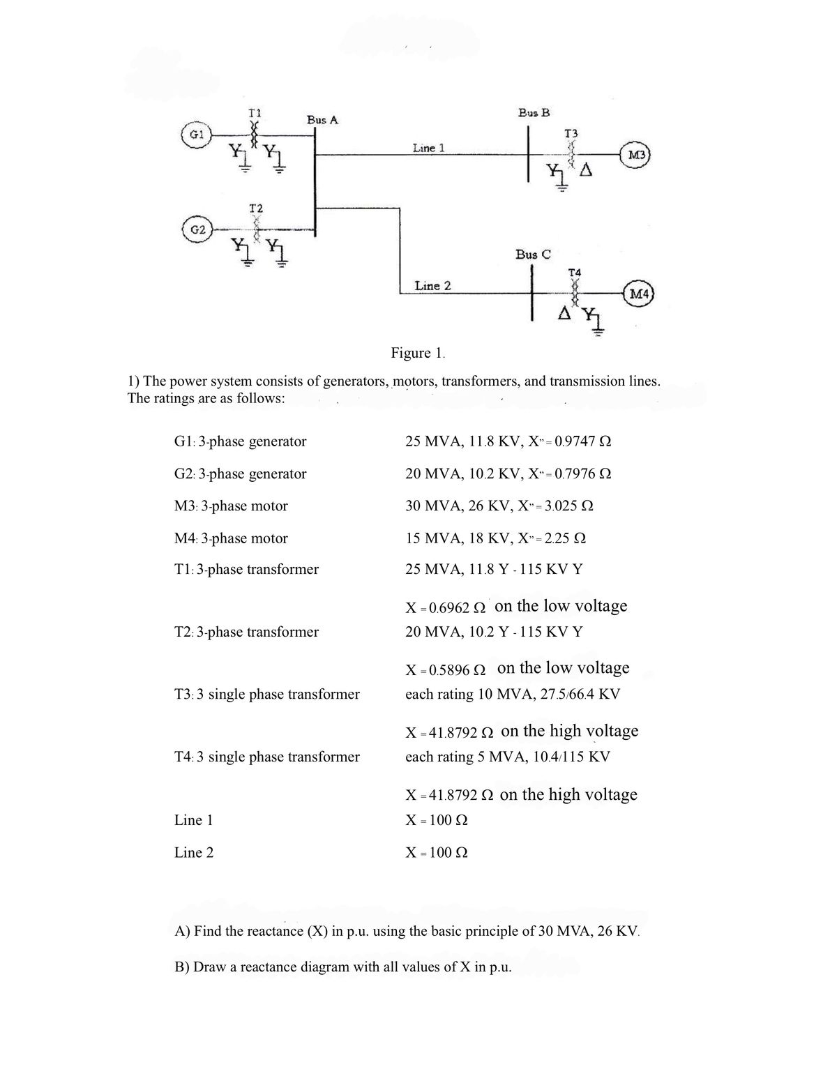
Figure 1.
1) The power system consists of generators, motors, transformers, and transmission lines.
The ratings are as follows:
G1: 3-phase generator
25 MVA, 11.8 KV, X" = 0.9747
G2:3-phase generator
20 MVA, 10.2 KV, X=0.7976
M3: 3-phase motor
M4: 3-phase motor
T1:3-phase transformer
T2: 3-phase transformer
T3:3 single phase transformer
T4:3 single phase transformer
Line 1
Line 2
30 MVA, 26 KV, X-3.025 Ω
15 MVA, 18 KV, X"-2.25 Ω
25 MVA, 11.8 Y - 115 KV Y
X = 0.6962 on the low voltage
20 MVA, 10.2 Y- 115 KV Y
X=0.5896 on the low voltage
each rating 10 MVA, 27.5/66.4 KV
X=41.8792 on the high voltage
each rating 5 MVA, 10.4/115 KV
X=41.8792 on the high voltage
Χ = 100 Ω
Χ = 100 Ω
A) Find the reactance (X) in p.u. using the basic principle of 30 MVA, 26 KV.
B) Draw a reactance diagram with all values of X in p.u.
Expert Solution
This question has been solved!
Explore an expertly crafted, step-by-step solution for a thorough understanding of key concepts.

Step by stepSolved in 2 steps with 4 images

Knowledge Booster

Similar questions
- Consider the three single-phase two-winding transformers shown in Figure 3.37. The high-voltage windings are connected in Y. (a) For the low-voltage side, connect the windings in , place the polarity marks, and label the terminals a, b, and c in accordance with the American standard. (b) Relabel the terminals a, b, and c such that VAN is 90 out of phase with Va for positive sequence.arrow_forward2) The power system consists of generators, motors, transformers, and transmission lines. The ratings are as follows: G1: 3-phase generator 25 MVA, 11 KV, X = 20% M1: 3-phase motor M2: 3-phase motor T1:3 single phase transformers T2: 3-phase transformer Line: 15 MVA, 13 KV, X = 25% 7.5 MVA, 13 KV, X = 25% Single phase transformer rating 30 MVA, 6.9/69 KV X = 10% Three phase transformer rating 30 MVA, 13.8/69 KV X = 10% Χ - 50 Ω = Τι G₁ 2. Line Figure 1. 3 T2 Σ M₁ Δι M2 Find the reactance (X) in p.u. units, given the base value of 25 MVA, 11 KV.arrow_forward1. A single-phase power system as shown in Figure 1 consists of a 240 V, 60 Hz generator supplying a load, Zod = 8 + j6 Q through a transmission line of impedance, Zne = 0.08 + j0.14 Q. Answer the following questions: (1) transformer, T; and T2. Determine the voltage at the load and transmission line losses without the (ii) Determine the voltage at the load and transmission line losses with the transformer, T, and T2. T1 T2 1:10 10:1 IG Zaine Zioad source Figure 1arrow_forward
- Equipment ratings and per-unit reactances for the system shown in the below figure are given as follows: Synchronous generators: GI 100 MVA 25 kV X1 = X2 = 0.2 Xo = 0.05 G2 100 MVA 13.8 kV X = X2 = 0.2 Xo =0.05 Transformers: TI 100 MVA 25/230 kV X = X2 = X, = 0.05 T2 100 MVA 13.8/230 kV X = X2 = Xo = 0.05 Transmission lines: TL12 100 MVA 230 kV X = X2 = 0.1 Xo =0.3 TL13 100 MVA 230 kV X = X2 = 0.1 Xo = 0.3 %3D TL23 100 MVA 230 kV X = X2 = 0.1 Xo = 0.3 %3D Using a 100-MVA, 230-kV base for the transmission lines, draw the per-unit sequene networks and reduce them to their Thévenin equivalents, “looking in" at bus 3. Neglect A-Y phase shifts. Compute the fault currents for a bolted three-phase fault at bus 3. 2 T2 b T1 TL12 to G1 G2 TL13 TL23 j0,03 j0,03 3arrow_forwardOne-line diagram of a power system is shown below. Relevant details are mentioned below. Generator: 100 MVA, 11 kV, 3-phase, reactance 20%; Transformer T1: 100 MVA, 10/132 kV, reactance 6%; Transformer T2: 80 MVA, 132/10 kV, reactance 5%; Line reactance is 100 Q. Motors M1 and M2 are rated at 50 MVA and 40 MVA respectively both at 10 kV and 20% reactance. In the above, reactances are per-phase values. Taking generator rating as base, draw the per- phase impedance diagram in which the elements need to be expressed in per unit. * T1 M, Transmission Line G M2) Aarrow_forwardProblem 1 - Series en Parallel AC networks [19] Look at the circuit in Figure 1 and determine the following: (a) Total Admittance. (b) Total Impedance. (c) Total Current (l:). (d) Current (I1) through impedance Z2. (e) Current (12) through impedance Z3. (f) Current (I3) through impedance Z4. (g) Is this an inductive or capacitive circuit? A. B Zs 220V;50HZ Figure 1 (h) Voltage across Z1. (i) Voltage across A and B. G) Voltage across Zs. Z1 = 3 + j5 ohm Z2 = 10 + jo ohm Z3 = 5 + j15 ohm Z4 = 10 – j30 ohm Zs = 20 – j30 ohm Admittance and Impedance in rectangular notation. All currents and voltage in polar notation. Take voltage as reference.arrow_forward
- b) Two synchronous generators, G2 and G2, are connected parallelly supplying a load. Generator G1 has a no-load frequency of 50.5 Hz and a slope of 300 MW/Hz. Generator G2 has a no-load frequency of 50.2 Hz and a slope of 500 MW/Hz. The load consumes 250 MW real power. (1) At what frequency does this system operate, and how much power is supplied by each of the two generators? (ii) An additional 100 MW load is added to this power system. What is the new system frequency, and how much power do G1 and G2 supply? (iii) The governor set point of G2 is changed to control system frequency back to 50 Hz. Determine the G2 governor set point.arrow_forwardQ2\ Two generators G1 & G2 are rated 15 MVA, 11 kV and 10 MVA, 11 kV respectively. The generators are connected to a transformer as shown in the following figure. Find the sub- transient current in each generator when a three-phase fault occurs on the high voltage side of the transformer. A/Y 15 MVA, 11 kV, X"gl=j0.10 pu G2 15 MVA, 11/66 kV, Xr-j0.06 pu 10 MVA, 11 kV, X"g2-j0.10 puarrow_forwardThe one-line diagram of an unloaded power system is shown below. T2 j 80 0 j 100 2 E Y uw Ts Reactances of the two sections of transmission line are shown in the diagram. The generators and transformers are rated as follows: Generator 1: 20 MVA, 13.8 kV, X" = 0.2 per unit Generator 2: 30 MVA, 18 kV, X = 0.2 per unit Generator 3: 30 MVA, 20 kV, X" = 0.2 per unit Transformer T1: 25 MVA, 220Y/13.8A kV, X = 10% Transformer T2: Single-phase units each rated 10 MVA, 127/18 kV, X = 10% Transformer T3: 35 MVA, 220Y/22Y kV, X = 10% Compute for the reactances per unit and by choosing a base of 50 MVA, 13.8kV in the circuit of generator 1. Show your complete solutions (41-48): 41. What is the generator 1 per unit reactance? a. 0.3333 b. 0.2755 c. 0.5 d. 0.2 42. What is the transformer 1 per unit reactance? a. 0.2 b. 0.1667 c. 0.1429 d. 0.0826 43. What is the transmission line 1 (point B to C) per unit reactance? a. 0.1033 b. 0.0826 c. 0.5 d. 0.2 44. What is the transformer 3 per unit reactance?…arrow_forward
- High voltage engineering subjectarrow_forwardPlease, I do not want a theoretical solution or using artificial intelligence. I want a solution on paper using the mathematical laws of the topicarrow_forwardConsider the oneline diagram shown in Figure 3.40. The three-phase transformer bank is made up of three identical single-phase transformers, each specified by X1=0.24 (on the low-voltage side), negligible resistance and magnetizing current, and turns ratio =N2/N1=10. The transformer bank is delivering 100 MW at 0.8 p.f. lagging to a substation bus whose voltage is 230 kV. (a) Determine the primary current magnitude, primary voltage (line-to-line) magnitude, and the three-phase complex power supplied by the generator. Choose the line-to-neutral voltage at the bus, Va as the reference Account for the phase shift, and assume positive-sequence operation. (b) Find the phase shift between the primary and secondary voltages.arrow_forward
arrow_back_ios
SEE MORE QUESTIONS
arrow_forward_ios
Recommended textbooks for you
- Power System Analysis and Design (MindTap Course ...Electrical EngineeringISBN:9781305632134Author:J. Duncan Glover, Thomas Overbye, Mulukutla S. SarmaPublisher:Cengage Learning
Power System Analysis and Design (MindTap Course ...
Electrical Engineering
ISBN:9781305632134
Author:J. Duncan Glover, Thomas Overbye, Mulukutla S. Sarma
Publisher:Cengage Learning