Introductory Circuit Analysis (13th Edition)
13th Edition
ISBN: 9780133923605
Author: Robert L. Boylestad
Publisher: PEARSON
expand_more
expand_more
format_list_bulleted
Question

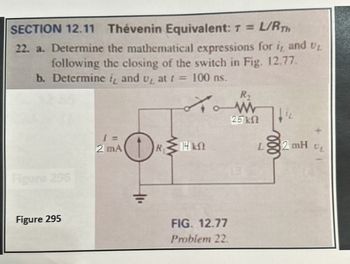
Transcribed Image Text:SECTION 12.11 Thévenin Equivalent: T = L/RTH
22. a. Determine the mathematical expressions for i, and UL
following the closing of the switch in Fig. 12.77.
b. Determine it and u₂ at f =
100 ns.
R,
Figure 296
W
25 ΚΩ
1 =
2 mA
R≤14 kN
ΚΩ
AL
Figure 295
FIG. 12.77
Problem 22.
L
2 mH
UL
Expert Solution
This question has been solved!
Explore an expertly crafted, step-by-step solution for a thorough understanding of key concepts.
Step by stepSolved in 2 steps with 1 images

Knowledge Booster
Similar questions
- Ge 10:1 m Thanks Any help will be appreciated. S BL • I am doing a AC DC 12 W Regulated power supply with 110 vrms and 60HZ as an input, and I need an output of 6v and 9 V. I have the designed already: the step-down transformer, Resistor as a current limiter to protect the Zener diode, a capacitor for the ripple voltage, and a 2 state switch ( when the switch is closed to the RL will give 9 V and when is closed to the S will give 6V as an output). • I need some support with some calculations to find PIV for each diode // Average Power// some calculations in how to find the values for the resistors and capacitors to accomplish the desire output // and some calculations for the ripple voltage. Note: the Zener is regulated to 9v. I know the RL>R to get the desire output.arrow_forwardSeries circuit on breadboard_9Volt battery source Can you draw where to connect: the multimeter leads,220 ohm resistor, 1N914 forward biased diode,jumper wires. I need to produce near 37mA and have failed to do so but only can produce 10.1mA.arrow_forwardA Homework 6b 03182022.docx.pdf - Adobe Reader File Edit View Window Help Tools Fill & Sign Comment Оpen 1 200% T Click on Tools to convert files to PDF. 1. A silicon p-n junction has the following parameters: Na = 1017/cm³, Na = 5 x10¹⁵/cm³, Diameter of the circular junction = 10 µm. Calculate Vbi, Xno, Xpo, W, Volume charge in the n-type depletion (qAxnoNp) and Emax at T=300K. 3:28 AM Type here to search 27°C W 24-Mar-22 ---arrow_forward
- Obtain the state-space model of the electrical system given below. Take the coil current and capacitor voltage as state variables and the voltage eo as the output variable.arrow_forwardQuèstion 14 Power supply circuit is delivering 0.5 A and an average voltage 20 V to the load as shown in the circuit below. The ripple voltage of the half wave rectifier is 0.5 V and the diode is represented using constant voltage model. The smoothing capacitor value is equal to L-Dc こosA 22V rmsら 50H2 RL VL-DC =20V 7. 0.01 F 0.02 F 0.0167 F None of the abovearrow_forwardhand written asap plzzzzz..i'll upvotearrow_forward
- 14. * If a long wire is connected to the terminals of a 12-V battery, 6.4 x 10¹⁹ electrons pass a cross section of the wire each second. Make a list of the physical quantities whose values you can determine using this information and determine three of them. Figure P19.35 R₂ www www A R3 + ww R₁ Warrow_forwardan | Schoc X O https://ti-submission-google.a x submission-google.app.schoology.com/assignment/student/59013660 M maaoun4@hawkm. Course: Student R.. Current Students.. 6 Home | Schoology M Inbox (2,780) - 20. Q Student Portal D DocHub - Circuits Lab Simulation - 10382745 * ew Insert Format Tools Add-ons Help Last edit was made 10 minutes ago by Zainab Chebib Comic San. A E = = = E E - E - E E 100% - Normal text 12 I 3 I.. 4 10. Keep Te vUTTery vurue Tre sume unu vuru uriTTIer puruneI Cirtur TIEXT TO TIE TrST puruner circuit using 3 light bulbs. 19. Compare the brightness of 2 light bulbs wired in parallel relative to the brightness of 3 light bulbs wired in parallel. Tap circuit element to edit. a. Based on the length of the light rays, when a third light bulb is added in parallel the brightness of each bulb MacBook Pro 吕口 F10 F7 F2 F4 & * %23 3 24 4. 5 6 E Y U D F G H J K Larrow_forwardECEarrow_forward
- in the attached photoarrow_forwardA sinusoidal source of 50 V rms drives the circuit. Use the offset diode model for asilicon diode.a. What is the maximum forward current? b. What is the peak inverse voltage across the diode?arrow_forward7- For the circuit below a) Find tbe time constant b) Sketch the waveforms for in, a when you close the switch AK 31m Harrow_forward
arrow_back_ios
SEE MORE QUESTIONS
arrow_forward_ios
Recommended textbooks for you
 Introductory Circuit Analysis (13th Edition)Electrical EngineeringISBN:9780133923605Author:Robert L. BoylestadPublisher:PEARSON
 Delmar's Standard Textbook Of ElectricityElectrical EngineeringISBN:9781337900348Author:Stephen L. HermanPublisher:Cengage Learning
 Programmable Logic ControllersElectrical EngineeringISBN:9780073373843Author:Frank D. PetruzellaPublisher:McGraw-Hill Education
 Fundamentals of Electric CircuitsElectrical EngineeringISBN:9780078028229Author:Charles K Alexander, Matthew SadikuPublisher:McGraw-Hill Education
 Electric Circuits. (11th Edition)Electrical EngineeringISBN:9780134746968Author:James W. Nilsson, Susan RiedelPublisher:PEARSON
 Engineering ElectromagneticsElectrical EngineeringISBN:9780078028151Author:Hayt, William H. (william Hart), Jr, BUCK, John A.Publisher:Mcgraw-hill Education,

Introductory Circuit Analysis (13th Edition)
Electrical Engineering
ISBN:9780133923605
Author:Robert L. Boylestad
Publisher:PEARSON

Delmar's Standard Textbook Of Electricity
Electrical Engineering
ISBN:9781337900348
Author:Stephen L. Herman
Publisher:Cengage Learning

Programmable Logic Controllers
Electrical Engineering
ISBN:9780073373843
Author:Frank D. Petruzella
Publisher:McGraw-Hill Education

Fundamentals of Electric Circuits
Electrical Engineering
ISBN:9780078028229
Author:Charles K Alexander, Matthew Sadiku
Publisher:McGraw-Hill Education

Electric Circuits. (11th Edition)
Electrical Engineering
ISBN:9780134746968
Author:James W. Nilsson, Susan Riedel
Publisher:PEARSON

Engineering Electromagnetics
Electrical Engineering
ISBN:9780078028151
Author:Hayt, William H. (william Hart), Jr, BUCK, John A.
Publisher:Mcgraw-hill Education,