Introductory Circuit Analysis (13th Edition)
13th Edition
ISBN: 9780133923605
Author: Robert L. Boylestad
Publisher: PEARSON
expand_more
expand_more
format_list_bulleted
Question
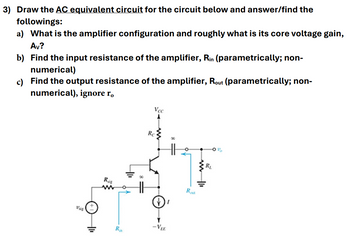
Draw the AC equivalent circuit for the circuit below and, the
followings:
a) What is the amplifier configuration and roughly what is its core voltage gain,
AV?
b) Find the input resistance of the amplifier, Rin (parametrically; non-numerical)
c) Find the output resistance of the amplifier, Rout (parametrically; non-numerical), ignore ro.

Transcribed Image Text:3) Draw the AC equivalent circuit for the circuit below and answer/find the
followings:
a) What is the amplifier configuration and roughly what is its core voltage gain,
Av?
b) Find the input resistance of the amplifier, Rin (parametrically; non-
numerical)
c) Find the output resistance of the amplifier, Rout (parametrically; non-
numerical), ignore ro
Vec
A
Re
Ri
Rot
Ra
-VEE
RL
Expert Solution
This question has been solved!
Explore an expertly crafted, step-by-step solution for a thorough understanding of key concepts.
Step by stepSolved in 2 steps with 6 images

Knowledge Booster
Similar questions
- Draw a n-p-n transistor connected in circuit common base (CB).Draw the input current-voltage characteristic, the output current-voltage characteristicsand the graph giving dependence of the output current as function of the input current.Define the amplification gain of this circuit.arrow_forwardC. Draw a n-p-n transistor connected in circuit common emitter (CE). Draw the input current-voltage characteristic, the output current-voltage characteristics and the graph giving dependence of the output current as function of the input current. Define the amplification gain of this circuit.arrow_forward+15 A00 AGND C₁ Ro C₂ Probe O-Scope + Rs. RG J1 R₁ Vout Figure 14: Common-Source Inverting Amplifier Probe GNDarrow_forward
- The transistor parameters for the circuit in Figure are B, =B2 = 100, VBE1on) = VBE2ton) = 0.7 V, and %3D VA1 =VA2 =0.Find the small signal voltage gain Av = vo/vs. (Note that V-=0.026 V) Vcc=9 V Rib Q1 Vs 1 ko -Ro 20 V 100 Q -wwarrow_forwardExplain amplifier characteristicsarrow_forwardexplain RC coupled amplifier in detail .arrow_forward
- 1. The DC-DC converter has several circuit configurations. a) (Draw a simple connection of IGBT switch, diode and inductor that can discriminate between Buck, Boost and Buck-Boost converter circuits respectively.) b) ('A Boost converter produces an output voltage, Vo that is more than or equal to the input voltage, Vi. Based on this statement develop the equation for the relationship between Vo Viand D. where D represents the duty ratio. You can use any suitable diagram to illustrate your answer.)arrow_forwardwhich of the following configurations has low impedance and high output impedance? a. common-base. c. common-collector. b. common-emitter. d. all of these.arrow_forward4) Consider the clamping circuit below, assume Vref=3 V and Vin=5sin(wt) ..Draw the output voltage waveform. Clearly mark the max and min of the voltage.. Vrefarrow_forward
- Using LTSpice, simulate the circuit below, use 2N3904 for the transistor. Part ! DC simulation: Measure VCE and Ic. Use .op for the simulation cmd. Remove all capacitors and input signals first. Part 2 AC simulation: Connect all capacitors now and apply an AC signal at the input with an amplitufe of 1mV and a frequency of 1kHz. Determine the Voltage gain of the circuit by dividing Vo with Vin. Show the output for both the DC and AC analysis. Take a screenshot of the circuit and the output voltages and waveforms. Paste in a word file, write your answers, then save as pdf. 50 kΩ Σ 20 0,5 ΚΩ wwwh 9 Vcc=20 V Ca=1 µF = Cc₂ Cg=50 μF 5.6 kn B=100 Ca IST • 3.3 ΚΩ 5 ΚΩΣ CEarrow_forwardI need help pls. I will give thumbs uparrow_forwardFind the following: DC gain, inductor current ripple and output voltage ripple: For DC-DC Buck converter: 1-Draw all circuits in all position 2-Sketch the transistor current waveform 3-Derive analytical expressions for the dc components of the capacitor voltages and inductor currents. 4-Derive analytical expressions for the peak ripple magnitudes of the input filter inductor current and capacitor voltage.arrow_forward
arrow_back_ios
SEE MORE QUESTIONS
arrow_forward_ios
Recommended textbooks for you
 Introductory Circuit Analysis (13th Edition)Electrical EngineeringISBN:9780133923605Author:Robert L. BoylestadPublisher:PEARSON
 Delmar's Standard Textbook Of ElectricityElectrical EngineeringISBN:9781337900348Author:Stephen L. HermanPublisher:Cengage Learning
 Programmable Logic ControllersElectrical EngineeringISBN:9780073373843Author:Frank D. PetruzellaPublisher:McGraw-Hill Education
 Fundamentals of Electric CircuitsElectrical EngineeringISBN:9780078028229Author:Charles K Alexander, Matthew SadikuPublisher:McGraw-Hill Education
 Electric Circuits. (11th Edition)Electrical EngineeringISBN:9780134746968Author:James W. Nilsson, Susan RiedelPublisher:PEARSON
 Engineering ElectromagneticsElectrical EngineeringISBN:9780078028151Author:Hayt, William H. (william Hart), Jr, BUCK, John A.Publisher:Mcgraw-hill Education,

Introductory Circuit Analysis (13th Edition)
Electrical Engineering
ISBN:9780133923605
Author:Robert L. Boylestad
Publisher:PEARSON

Delmar's Standard Textbook Of Electricity
Electrical Engineering
ISBN:9781337900348
Author:Stephen L. Herman
Publisher:Cengage Learning

Programmable Logic Controllers
Electrical Engineering
ISBN:9780073373843
Author:Frank D. Petruzella
Publisher:McGraw-Hill Education

Fundamentals of Electric Circuits
Electrical Engineering
ISBN:9780078028229
Author:Charles K Alexander, Matthew Sadiku
Publisher:McGraw-Hill Education

Electric Circuits. (11th Edition)
Electrical Engineering
ISBN:9780134746968
Author:James W. Nilsson, Susan Riedel
Publisher:PEARSON

Engineering Electromagnetics
Electrical Engineering
ISBN:9780078028151
Author:Hayt, William H. (william Hart), Jr, BUCK, John A.
Publisher:Mcgraw-hill Education,