Delmar's Standard Textbook Of Electricity
7th Edition
ISBN: 9781337900348
Author: Stephen L. Herman
Publisher: Cengage Learning
expand_more
expand_more
format_list_bulleted
Question
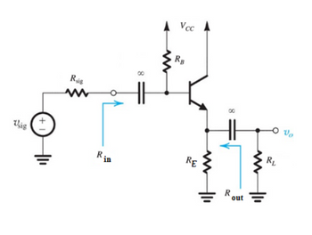
Draw the AC equivalent circuit for the circuit shown

Transcribed Image Text:Rais
www
8
▲ Vcc ▲
ww
RB
Usig
Rin
RE
www
R
out
RL
Expert Solution
This question has been solved!
Explore an expertly crafted, step-by-step solution for a thorough understanding of key concepts.
Step by stepSolved in 2 steps with 3 images

Knowledge Booster
Similar questions
- What is CEMF?arrow_forwardA "T" type thermocouple has linear calibration between 0 "C and 400 °C with voltage at maximum temperature, with reference junction at 0 °C, equal to 20.68 mV. i) Determine the correction which must be made to the indicated voltage when cold junction temperature is at 25 °C. ii) If the indicated voltage is 8.92 mV, find temperature at hot function.arrow_forwardHow would you add the thermal interfaces of a heatsink using the concept of thermal resistance? Specifically the thermal resistance between ambient temperature and the case of the IC and the case of the IC and the junction of the IC. 1. RCA in series with RJC or 2. RCA in parallel with RJCarrow_forward
- The time period of the output voltage of a single phase bridge rectifier is 25/3 ms. The supply frequency will be _____ Hz.arrow_forwardFind VDc if VAN = VBN = VCN= 120 volts... Half-wave Three-phase Rectifier Conduction Waveform Periodic Time (T) A B 180 360 90° 450 540 time 270 VAN VeN VAN VEN Voc Vrc 30 120 150 270 390 510° time Output Voltage Waveform Barrow_forwardlp ET v aph S Normal No Spacing Heading 1 Heading 2 Styles Ti The nominal output voltage of a certain regulator is 8 V. The output changes by 2 mV when the input voltage rises from 12v to 18V. Complete the following: a. Determine the line regulation and express it as a percentage change. b. Express the line regulation in %/V.arrow_forward
- CT -2: Answer all partsarrow_forwardFAIRCHILD Discrete POWER & Signal Technologies SEMICONDUCTOR ru 1N4001 - 1N4007 Features • Low torward voltage drop. 10 a14 * High aurge eurrent cepablity. 0.160 4.06) DO 41 COLOR BAND DGNOTEs CAT-Cos 1.0 Ampere General Purpose Rectifiers Absolute Maximum Ratings T-26*Cuness atnerwioe rated Symbol Parameter Value Units Average Recttied Current 1.0 375" lead length a TA - 75°C Tsargei Peak Forward Surge Current 8.3 ms single halr-sine-wave Superimposed on rated load JEDEC method) 30 A Pa Total Device Dissipetion 2.5 20 Derste above 25°C Ra Tag Thermal Resistence, Junction to Amblent 5D Storage Temperature Range 55 to +175 -55 to +150 Operating Junetion Temperature PC "These rarings are imithg valuee above whien the serviceatity or any semiconductor device may te impaired. Electrical Characteristics T-20'Cunieas ofherwise roted Parameter Device Units 4001 4002 4003 4004 4005 4006 4007 Peak Repetitive Reverse Vellage Maximum RME votage DC Reverse Voltage Maximum Reverse Current @ rated VR…arrow_forwardA 60 Hz sinusoidal voltage with an RMS value of 120 V is applied to a single-phase full-wave SCR rectifier. The DC output voltage of the rectifier is 101 V, the firing angle (in degrees) of SCR is would be: O A. 36 O B. 45 O C. None of the other choices are correct O D. 30 O E. 60arrow_forward
arrow_back_ios
SEE MORE QUESTIONS
arrow_forward_ios
Recommended textbooks for you
 Delmar's Standard Textbook Of ElectricityElectrical EngineeringISBN:9781337900348Author:Stephen L. HermanPublisher:Cengage Learning

Delmar's Standard Textbook Of Electricity
Electrical Engineering
ISBN:9781337900348
Author:Stephen L. Herman
Publisher:Cengage Learning