
Introductory Circuit Analysis (13th Edition)
13th Edition
ISBN: 9780133923605
Author: Robert L. Boylestad
Publisher: PEARSON
expand_more
expand_more
format_list_bulleted
Related questions
Question
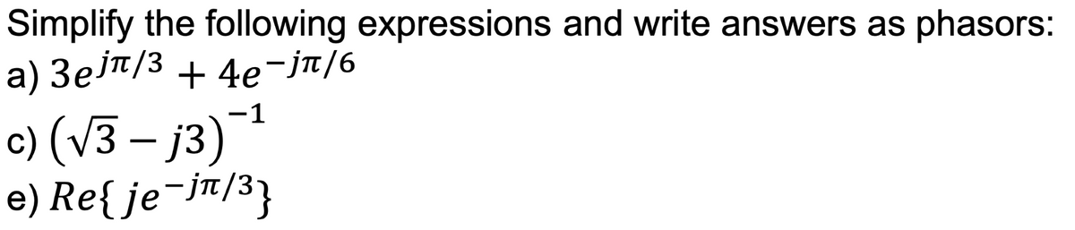

Transcribed Image Text:Simplify the following expressions and write answers as phasors:
a) 3еjл/³ +4е¯jπ/6
-1
c) (√3 - j3)¯¹
e) Re{ je¯jπ/³}
Expert Solution
This question has been solved!
Explore an expertly crafted, step-by-step solution for a thorough understanding of key concepts.

Step by stepSolved in 2 steps with 1 images

Knowledge Booster

Similar questions
- - Required information NOTE: This is a multi-part question. Once an answer is submitted, you will be unable to return to this part. Perform the indicated operations, and express the answer in both rectangular and polar forms. 2+j3 1+8/90° Report your answer so that all angles are in the range of 0 degrees to positive 180 degrees. The rectangular form for the given function is The polar form for the given function is 10arrow_forwardWhat can be the observations regarding frequency in this waveform? What is the frequency in this waveform? Explain how.arrow_forwardQUESTION 3 An inductor, a capacitor, and a resistor are connected in series with a function generator. The inductor drops 5V RMS, the capacitor drops 20V RMS, and the resistor drops 2V RMS. Find the magnitude of the total voltage. O 27V RMS O 15V RMS O 38V RMS O 9V RMSarrow_forward
- QUESTION 3 An inductor, a capacitor, and a resistor are connected in parallel with a function generator. The inductor draws 100mA RMS, the capacitor draws 150mA RMS, and the resistor draws 200mA RMS. Find the magnitude of the total current. O 450mA RMS O 544mA RMS O 352mA RMS O 206mA RMSarrow_forwardPerform the indicated operations, and express the answer in both rectangular and polar forms. 2+j3 1+8/90° Report your answer so that all angles are in the range of 0 degrees to positive 180 degrees. The rectangular form for the given function is The polar form for the given function is 8 2- Oarrow_forwardin V1 R2 100k SINE(0 10 100) R1 100k D1 D V2 0 out D D2 V3 0 DC offset[V]: 0 Amplitude[V]: 10 Freq[Hz]: 100 T delay[s]: Theta[1/s]: Phi[deg]: Ncycles: anter 2019-2220 Figure 3-5 Clipper Circuit for LTSPICE Simulation C4. To specify the type of simulation, select "Simulate>>Edit Simulation Cmd" from the menu. Choose "Transient" and enter 30m for Stop time, 0 for Time to start saving data, and 1m for Maximum Timestep. Click OK. C5. Click Run to start the analysis. C6. Place two voltage probes (voltage probes appear when placed on a wire during simulation), one at the input side (at the top of V1) and another at the output side (at the top of D2) of the circuit. What difference do you observe between the input and the output waveforms?arrow_forward
- Convert the complex number Z = 3 +4i into a. Polar form b. Trigonometric form c. Exponential Formarrow_forwardTyping solution please I will like it please ASAP Pleasearrow_forwardDerive an expression for Vout as a function of Vin, where Vin is the nodes connected to the Waveform Generator signal. Show your equations below, either typed or a picture of your handwritten work.arrow_forward
- form: Express The following Complex numbers in rectangular № 2, b) Z₂ = -3e-jπ/4 c) 23 = √ 3 e d 24 11 -j 25 = ==J 3 -4 2 -j3π/4 f) 26 = (2 + j) 9) 2₂ = (3-j2)³ g D 27 AAA D A 35arrow_forwardPlease explain in step by step detail how to answer and solve this problemarrow_forwardFor the resistor shown above what best describes its behavior at 1 MHz? It responds primarily as a resistor It responds primarily as a capacitor O It responds primarily as a inductor It responds primarily as a transformerarrow_forward
arrow_back_ios
SEE MORE QUESTIONS
arrow_forward_ios
Recommended textbooks for you
- Introductory Circuit Analysis (13th Edition)Electrical EngineeringISBN:9780133923605Author:Robert L. BoylestadPublisher:PEARSON
 Delmar's Standard Textbook Of ElectricityElectrical EngineeringISBN:9781337900348Author:Stephen L. HermanPublisher:Cengage Learning
 Programmable Logic ControllersElectrical EngineeringISBN:9780073373843Author:Frank D. PetruzellaPublisher:McGraw-Hill Education
  Fundamentals of Electric CircuitsElectrical EngineeringISBN:9780078028229Author:Charles K Alexander, Matthew SadikuPublisher:McGraw-Hill Education
 Electric Circuits. (11th Edition)Electrical EngineeringISBN:9780134746968Author:James W. Nilsson, Susan RiedelPublisher:PEARSON
 Engineering ElectromagneticsElectrical EngineeringISBN:9780078028151Author:Hayt, William H. (william Hart), Jr, BUCK, John A.Publisher:Mcgraw-hill Education,
Introductory Circuit Analysis (13th Edition)
Electrical Engineering
ISBN:9780133923605
Author:Robert L. Boylestad
Publisher:PEARSON
Delmar's Standard Textbook Of Electricity
Electrical Engineering
ISBN:9781337900348
Author:Stephen L. Herman
Publisher:Cengage Learning
Programmable Logic Controllers
Electrical Engineering
ISBN:9780073373843
Author:Frank D. Petruzella
Publisher:McGraw-Hill Education
Fundamentals of Electric Circuits
Electrical Engineering
ISBN:9780078028229
Author:Charles K Alexander, Matthew Sadiku
Publisher:McGraw-Hill Education
Electric Circuits. (11th Edition)
Electrical Engineering
ISBN:9780134746968
Author:James W. Nilsson, Susan Riedel
Publisher:PEARSON
Engineering Electromagnetics
Electrical Engineering
ISBN:9780078028151
Author:Hayt, William H. (william Hart), Jr, BUCK, John A.
Publisher:Mcgraw-hill Education,