Introductory Circuit Analysis (13th Edition)
13th Edition
ISBN: 9780133923605
Author: Robert L. Boylestad
Publisher: PEARSON
expand_more
expand_more
format_list_bulleted
Question
thumb_up100%
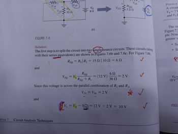
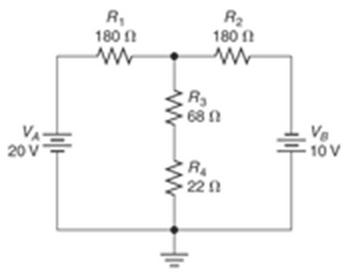
- Determine the values of V1 through V4 for the circuits shown in the following figure (Fig. 7.43b). I believe this Superposition Theorem. The circuit below has 4 resistors but my examples have only 3. The question seems ask for the voltage values but others have included current values. I do not know how to calculate V4. I am not sure if I use the equivalent of V3||V4 for V3 and V4 voltage. I will leave example photos out my book but it does not show how to do V4.

Transcribed Image Text:www
V₁B
+
V3B
+
R3
W
10 Ω
V2B
VB
9 V
+
REQ
V2B
VEQ
7.5 Ω
9V
Practice
A circuit
VB=7\
and V3 f
FIGURE 7.6
Solution:
One(c)
The first step is to split the circuit into two single source circuits. These circuits (along
with their series equivalents) are shown in Figures 7.6b and 7.6c. For Figure 7.6b,
REQ = R2|| R3 = 15 || 10
= 6N
The re
Figure 7.7
ple. Note
greater v
. Si
.Si
andum
REQ
6 Ω
VEQ = VA REQ + R₁
=
= (12 V)
=2V
36 Ω
Since this voltage is across the parallel combination of R2 and R3,
V2A = V3A = 2 V
ЗА
and
PTER 7
Circuit Analysis Techniques
V₁ = VA - VEQ = 12 V-2 V = 10 V
✓
VA-
12 V
FIGU

Transcribed Image Text:R₁
180
ww
20
20 V
÷
R₂
180
www
R₂
680
VB
10 V
ww
www
R
220
Expert Solution
This question has been solved!
Explore an expertly crafted, step-by-step solution for a thorough understanding of key concepts.
Step by stepSolved in 2 steps with 5 images

Knowledge Booster
Similar questions
- 2. An Automatic Night Light uses a photocell to detect the amount of available light in a room. Under strong light the resistance of the photocell is 1kn but goes up to 100k2 in total darkness. The photocell is put in series with a 4.7k2 resistor so as to make a voltage divider when the ends are connected between +5V and GND as shown. As it gets darker in the room, the resistance of the photocell goes up and raises the voltage on the "Sensor Voltage" line. At "dusk", the photocell has a resistance of 10k2. Automatic Night Light 5v Vdd a. What will the range of the sensor voltage be as the photocell +5V goes from 1k2 (bright light) to 100k2 (total darkness)? Photocell b. Write the equation for VoUT expressed in terms of the op-amp Sensor Voltage LM358AD Vout U1A mmarceau 5V inputs and gain. What is the maximum range for Vour? Reference R4 24.7ka Voltage (V) White LED C. Assuming the light is to come on at "dusk", what must the POTENTIOMETER reference voltage be set to to have the LED…arrow_forwardA moving coil ammeter gives a full scale deflection for a current i = 250 mA and its coil has a resistance RC = 0.75 Ω. It is provided with a multiplier resistance Rm that allows a voltage measurement of up to 5 V. What is the value of the multiplier resistance?arrow_forwardA moving coil ammeter gives a full scale deflection for a current i = 300 mA and its coil has a resistance RC = 1Ω. To use this ammeter as a voltmeter that measures 9V at full scale deflection a multiplier resistance, RM, is added in series with the coil. What is the value of the multiplier resistance? Select one: a. 31 Ω b. 32 Ω c. 30 Ω d. 29 Ωarrow_forward
- A battery with EMF of 7V and an internal resistance, r=0.08 is connected to a load resistance R=240. Determine its terminal voltage. r www + M Rarrow_forwardfig. 7.80 for the Gufiguration of © find the currents I2, Is andl Is 5 find the Joltages Vy and us Ri R3 Ru R6 Rs R7 Ri 302 32arrow_forwardExercice 60: In Figure 7.92, the ammeter reads 2.0 A and the volmeter reads 2.0 V. Use this information to find the value of the unknown resistance R as well as the currents ?1 and ?2. The potential at the terminal of measuring devices identified by a + is higher than the potential at the terminal identified by a -. Answer: R= 3.00 Ohms, ?1 = 2.00 A, ?2= 4.00 A Please show steps, formulas and explanations for my own understandingarrow_forward
- All information about current transformer and voltage transformer in protection systemarrow_forwardA PV system uses 720 silicon PV cells connected in an array which supplies up to 120 V. .How many PV cells are connected in series if 120 V are needed and one cell delivers 0.5 V? O a. 240 O b. 120 O c. 360 O d. 60arrow_forward7.1arrow_forward
- Superposition V. Determine the current flowing through (Ix) and voltage across the 2 ohms resistor (Vx) a.) 3V acting alone a.1) Draw the circuit with 3v acting alone a.2) Solve to find Ix' and Vx' b.) 4A acting alone b.1) draw the circuit with 4A acting alone b.2) use circuit simulation software( NI Multisim, or Multisim live, or Everycircuit) simulate circuit (from b.1) and add properly ammeter and voltmeter to find Ix'' and Vx'' with 4A acting alone b.3.) Solve to find Ix'' and Vx'' (manually) c.) solve for Ix and Vx from results of (a.1, a.2, b.2) d.) simulate the original given circuit (with 3v and 4A) to check the results (from c, for Ix and Vx)arrow_forward19. measure the values across R1 and R3 and confirm VMAX and VMIN from Step 16 using the voltage divider principle. Insert an image of your calculations below. Include a circuit diagram with your calculations. Using the maths demonstrated above, what would be the values of R1 and R3 to achieve minimum and maximum voltages of 0.3V and E-0.3V, respectively. Show your calculations below.arrow_forward
arrow_back_ios
arrow_forward_ios
Recommended textbooks for you
 Introductory Circuit Analysis (13th Edition)Electrical EngineeringISBN:9780133923605Author:Robert L. BoylestadPublisher:PEARSON
 Delmar's Standard Textbook Of ElectricityElectrical EngineeringISBN:9781337900348Author:Stephen L. HermanPublisher:Cengage Learning
 Programmable Logic ControllersElectrical EngineeringISBN:9780073373843Author:Frank D. PetruzellaPublisher:McGraw-Hill Education
 Fundamentals of Electric CircuitsElectrical EngineeringISBN:9780078028229Author:Charles K Alexander, Matthew SadikuPublisher:McGraw-Hill Education
 Electric Circuits. (11th Edition)Electrical EngineeringISBN:9780134746968Author:James W. Nilsson, Susan RiedelPublisher:PEARSON
 Engineering ElectromagneticsElectrical EngineeringISBN:9780078028151Author:Hayt, William H. (william Hart), Jr, BUCK, John A.Publisher:Mcgraw-hill Education,

Introductory Circuit Analysis (13th Edition)
Electrical Engineering
ISBN:9780133923605
Author:Robert L. Boylestad
Publisher:PEARSON

Delmar's Standard Textbook Of Electricity
Electrical Engineering
ISBN:9781337900348
Author:Stephen L. Herman
Publisher:Cengage Learning

Programmable Logic Controllers
Electrical Engineering
ISBN:9780073373843
Author:Frank D. Petruzella
Publisher:McGraw-Hill Education

Fundamentals of Electric Circuits
Electrical Engineering
ISBN:9780078028229
Author:Charles K Alexander, Matthew Sadiku
Publisher:McGraw-Hill Education

Electric Circuits. (11th Edition)
Electrical Engineering
ISBN:9780134746968
Author:James W. Nilsson, Susan Riedel
Publisher:PEARSON

Engineering Electromagnetics
Electrical Engineering
ISBN:9780078028151
Author:Hayt, William H. (william Hart), Jr, BUCK, John A.
Publisher:Mcgraw-hill Education,