Introductory Circuit Analysis (13th Edition)
13th Edition
ISBN: 9780133923605
Author: Robert L. Boylestad
Publisher: PEARSON
expand_more
expand_more
format_list_bulleted
Question

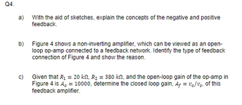
Transcribed Image Text:Q4.
a)
With the aid of sketches, explain the concepts of the negative and positive
feedback.
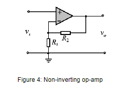
b) Figure 4 shows a non-inverting amplifier, which can be viewed as an open-
loop op-amp connected to a feedback network. Identify the type of feedback
connection of Figure 4 and show the reason.
Given that R₁ = 20 kn, R₂ = 380 kn, and the open-loop gain of the op-amp in
Figure 4 is A, = 10000, determine the closed loop gain, A+ = vo/v₂, of this
feedback amplifier.

Transcribed Image Text:V₁
R₁
R₂
Figure 4: Non-inverting op-amp
Expert Solution
This question has been solved!
Explore an expertly crafted, step-by-step solution for a thorough understanding of key concepts.
Step by stepSolved in 2 steps with 2 images

Knowledge Booster
Similar questions
- An operational-amplifier circuit that may be used as a controller is shown in Figure Qla. (a) R4 ww R1 R3 e Co Figure Qla R1, R2, R3 and R4 are resistors and C1 and C2 are capacitors. Assume both op-amps are ideal and their input/output voltages are ei, e and eo, as shown in the Figure. Using the impedance approach: (i) obtain the transfer function for each op-amp, i.e. E(s)/E:(s) and Eo(s)/E(s). (ii) hence obtain the complete transfer function for the system, i.e. Eo(s)/Ei(s). (iii) Determine D(s) = Eo(s)/E:(s) when R1 = R2 = R3 = R4 = 1 N and C1=1 F, C2= 2 F. %3D (b) Consider the closed-loop control system shown in Figure Qlb. 1 Σ K.D(s) (s +2) Figure Qlb K is the gain and D(s) is the transfer function obtained in part (a)-iii. (i) Plot open loop zeros and poles for the above system in the s-plane. [. Determine whether the point (-1+j) is a closed loop pole for any value of K, by considering the angle criterion at this point. (ii) (c) Briefly summarise the steps, which need to be…arrow_forwarda) Two feedback configurations are shown in Figures Q1.a(i) and Q1.a(ii). Derive the closed-loop gain Af in each case. V₁. V₁. A1 B1 Figure Q1.a(i) A₁ B₁ Figure Q1.a(ii) A₂ A₂ B₂ ܘܢ -Varrow_forward4. (a) Determine the input and output impedances of the amplifier in Figure - 2. The op-amp datasheet gives ZIN = 1.2 MQ, ZoUT = 120 Q, and AOL = 150,000. (b) Find the closed-loop voltage gain. Department of Computer & Network Engineering, College of Computer Science & Information Technology Vin Vout R 240 k.N R; 10 kN Figure - 2arrow_forward
arrow_back_ios
arrow_forward_ios
Recommended textbooks for you
 Introductory Circuit Analysis (13th Edition)Electrical EngineeringISBN:9780133923605Author:Robert L. BoylestadPublisher:PEARSON
 Delmar's Standard Textbook Of ElectricityElectrical EngineeringISBN:9781337900348Author:Stephen L. HermanPublisher:Cengage Learning
 Programmable Logic ControllersElectrical EngineeringISBN:9780073373843Author:Frank D. PetruzellaPublisher:McGraw-Hill Education
 Fundamentals of Electric CircuitsElectrical EngineeringISBN:9780078028229Author:Charles K Alexander, Matthew SadikuPublisher:McGraw-Hill Education
 Electric Circuits. (11th Edition)Electrical EngineeringISBN:9780134746968Author:James W. Nilsson, Susan RiedelPublisher:PEARSON
 Engineering ElectromagneticsElectrical EngineeringISBN:9780078028151Author:Hayt, William H. (william Hart), Jr, BUCK, John A.Publisher:Mcgraw-hill Education,

Introductory Circuit Analysis (13th Edition)
Electrical Engineering
ISBN:9780133923605
Author:Robert L. Boylestad
Publisher:PEARSON

Delmar's Standard Textbook Of Electricity
Electrical Engineering
ISBN:9781337900348
Author:Stephen L. Herman
Publisher:Cengage Learning

Programmable Logic Controllers
Electrical Engineering
ISBN:9780073373843
Author:Frank D. Petruzella
Publisher:McGraw-Hill Education

Fundamentals of Electric Circuits
Electrical Engineering
ISBN:9780078028229
Author:Charles K Alexander, Matthew Sadiku
Publisher:McGraw-Hill Education

Electric Circuits. (11th Edition)
Electrical Engineering
ISBN:9780134746968
Author:James W. Nilsson, Susan Riedel
Publisher:PEARSON

Engineering Electromagnetics
Electrical Engineering
ISBN:9780078028151
Author:Hayt, William H. (william Hart), Jr, BUCK, John A.
Publisher:Mcgraw-hill Education,