
Introductory Circuit Analysis (13th Edition)
13th Edition
ISBN: 9780133923605
Author: Robert L. Boylestad
Publisher: PEARSON
expand_more
expand_more
format_list_bulleted
Related questions
Question
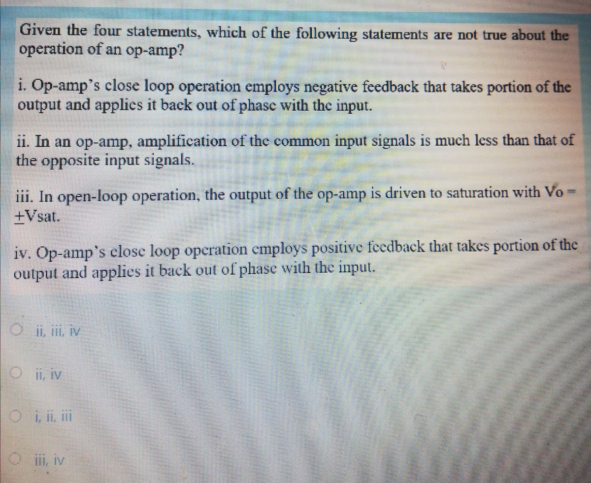

Transcribed Image Text:Given the four statements, which of the following statements are not true about the
operation of an op-amp?
i. Op-amp's close loop operation employs negative feedback that takes portion of the
output and applics it back out of phase with the input.
11. In an op-amp, amplification of the common input signals is much less than that of
the opposite input signals.
iii. In open-loop operation, the output of the op-amp is driven to saturation with Vo =
+Vsat.
iv. Op-amp's close loop operation employs positive feedback that takes portion of the
output and applics it back out of phase with the input.
O i, iv
Expert Solution
This question has been solved!
Explore an expertly crafted, step-by-step solution for a thorough understanding of key concepts.

Step by stepSolved in 2 steps with 2 images

Knowledge Booster


Learn more about
Need a deep-dive on the concept behind this application? Look no further. Learn more about this topic, electrical-engineering and related others by exploring similar questions and additional content below.Similar questions
- i. The saturation voltage an op-amp is primarily controlled by(i) power supply (+Vcc and -Vcc)(ii) open-loop gain of the op-amp(iii) common mode gain (iv) slew ratearrow_forwardhas been determined that a certain op-amp has three internal critical frequencies, as follow 1.2 kHz, 50 kHz, and 250 kHz. If the midrange open-loop gain is 100 dB, is the amplifier configuration stable, marginally stable, or unstable?arrow_forwardFigure 3 shows a Hartley oscillator. Assume that the op-amp employed in the figure is an ideal op-amp, and R1= 20 kΩ, R2 = 60 kΩ, L1=10 mH. b) State the Barkhausen criterion for sustained oscillation.c) Explain briefly how the phase shift requirement for sustained oscillation ismet in the circuit of Figure 3.d) The feedback ratio and oscillation frequency of Figure 3 are givenrespectively by, B = -L2/L1 and w0 = 1 / sqrt(L1 +L2)C Determine the values of C and L2 in order for the circuit to oscillate at a frequency of 200 Hz.arrow_forward
arrow_back_ios
arrow_forward_ios
Recommended textbooks for you
- Introductory Circuit Analysis (13th Edition)Electrical EngineeringISBN:9780133923605Author:Robert L. BoylestadPublisher:PEARSON
 Delmar's Standard Textbook Of ElectricityElectrical EngineeringISBN:9781337900348Author:Stephen L. HermanPublisher:Cengage Learning
 Programmable Logic ControllersElectrical EngineeringISBN:9780073373843Author:Frank D. PetruzellaPublisher:McGraw-Hill Education
  Fundamentals of Electric CircuitsElectrical EngineeringISBN:9780078028229Author:Charles K Alexander, Matthew SadikuPublisher:McGraw-Hill Education
 Electric Circuits. (11th Edition)Electrical EngineeringISBN:9780134746968Author:James W. Nilsson, Susan RiedelPublisher:PEARSON
 Engineering ElectromagneticsElectrical EngineeringISBN:9780078028151Author:Hayt, William H. (william Hart), Jr, BUCK, John A.Publisher:Mcgraw-hill Education,
Introductory Circuit Analysis (13th Edition)
Electrical Engineering
ISBN:9780133923605
Author:Robert L. Boylestad
Publisher:PEARSON
Delmar's Standard Textbook Of Electricity
Electrical Engineering
ISBN:9781337900348
Author:Stephen L. Herman
Publisher:Cengage Learning
Programmable Logic Controllers
Electrical Engineering
ISBN:9780073373843
Author:Frank D. Petruzella
Publisher:McGraw-Hill Education
Fundamentals of Electric Circuits
Electrical Engineering
ISBN:9780078028229
Author:Charles K Alexander, Matthew Sadiku
Publisher:McGraw-Hill Education
Electric Circuits. (11th Edition)
Electrical Engineering
ISBN:9780134746968
Author:James W. Nilsson, Susan Riedel
Publisher:PEARSON
Engineering Electromagnetics
Electrical Engineering
ISBN:9780078028151
Author:Hayt, William H. (william Hart), Jr, BUCK, John A.
Publisher:Mcgraw-hill Education,