
Elements Of Electromagnetics
7th Edition
ISBN: 9780190698614
Author: Sadiku, Matthew N. O.
Publisher: Oxford University Press
expand_more
expand_more
format_list_bulleted
Related questions
Concept explainers
Question
thumb_up100%

Transcribed Image Text:1%17 l. I.
HWZ_23801310677T..
18 at 8:30 AM
Class
Tuesday 12:30PM-2:30PM
& Thursday 8:30AM-10:30AM
Page3
Engineering Mechanics: Statics (EI13)
First Semester, First year. Academic year 2020-2021
Department of Civil Engineering
College of Engineering
Univensity of Misan
Course link on Moodle:
https://www.uomisan.edu.iq/moodle/course/view.php?id=597
Instructor: Dr. Murtada Abass
Assignment Due date:
February 18.2021 at 8:30
AM
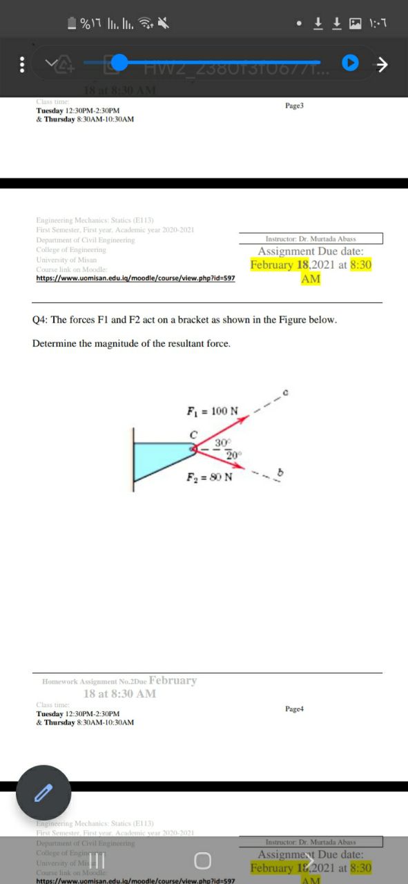
F1
act on a brac
as shown in
Figure below.
Determine the magnitude of the resultant force.
F = 100 N
30
20
F = 80 N
Homework Assigument No.2Due February
18 at 8:30 AM
Class time:
Page4
Tuesday 12:30PM-2:30PM
& Thursday 8:30AM-10:30AM
Lngineering Mechanics: Statics (E13)
First Semester. First veur. Acdemic vear 2020-2021
Depurtment of Civil Engineering
College of Enginn
University of Mis
Course link on Moodle
https://www.uomisan.edu.ig/moodle/course/view.php?id=597
Instructor: Dr. Murtada Abass
Assignment Due date:
February 18.2021 at 8:30
AM
Expert Solution
This question has been solved!
Explore an expertly crafted, step-by-step solution for a thorough understanding of key concepts.

Step by stepSolved in 2 steps with 2 images

Knowledge Booster


Learn more about
Need a deep-dive on the concept behind this application? Look no further. Learn more about this topic, mechanical-engineering and related others by exploring similar questions and additional content below.Similar questions
- The forces acting on the arm of an athlete doing shoulder exercises are shown in the figure. The athlete holds his arm at an angle of β = 30° with the horizontal axis . Point O represents the axis of rotation in the shoulder joint, point A represents the connection point of the deltoid muscle to the humerus, point B represents the center of gravity of the arm, and point C represents the application point of the force acting on the hand. The distances between the rotation axis (O point) of the shoulder joint and the points A, B and C are a=22 cm , b =33 cm and c= 60 cm , respectively . A force of F= 120 N, which makes an angle of γ=30° with the vertical from the point C, acts on the athlete's hand . Weight of the athlete's armW= 80 N. The direction of application of the Fm muscle force makes an angle of α=20° with the longitudinal axis of the arm. According to this; a) Calculate the muscle strength F M b) Calculate the angle θ of the joint reaction force F J with the horizontal.…arrow_forwardF₁ Him - F2 | m F₁ + ן F3 -1 m-arrow_forwardThree cables are tightened to an eyebolt as shown in the figure. Determine the resultant force and its direction, exerted by the forces of the three cables.arrow_forward
- Determine the magnitude and direction of the resultant for system of forces shown in the figure. Take F1 = 99.6 N, F2 = 43.7 N, F3 = 84.2 N, F4 = 66.0 N, F5 = 88.6 N, α = 29.8°, β = 50.2°, and γ = 55.1°. Sum of all horizontal force components, ΣH (N) = Sum of all Vertical force components, ΣV (N) = The resultant force, R (N) = The direction of the resultant force, θ (Degree) =arrow_forward2 m F₂ = 40 N T 3 m A F₁ = 70 N 3 m C -3 m 4 m x 2m B Determine the magnitude of the projection of the force F₁ along cable AC. Determine the angle between the two ropes.arrow_forwardFind the magnitude and direction of the resultant force for the system of forces shown in the figure. Where F =25 N, F2 =20N, F3 =20N, F4 =50N, F5 = 20N & F6 =40N. The angles 0, =15°, 83 =35° , 04 = 40°, 06 = 40 ° (Enter only the values in the boxes by referring the units given in bracket) F2 F3 + F1 F6 F4 Fs (1) The horizontal component 2H of the given system is (unit is in N) = (2) The vertical component 2 V of the given system is (unit is in N) = (3) The resultant of the given force system is (unit in N) = (4) The direction of Resultant is (in°) =arrow_forward
- Q7. Determine the resultant force and angle of the forces as shown in figure by (components method the x-horizontal component and y-vertical components)? F2= 80 N 20 F = 150 N 30° 15° F=100 N F=110 Narrow_forwardConsider the frame shown in (Figure 1). Suppose that F1 = 8 kN . Determine the x and y components of the force that the pin at B exerts on the frame using scalar notation. Determine the x and y components of the force that the pin at A exerts on the frame using scalar notation.arrow_forwardDetermine the magnitude of the force exerted by the cable at B of the bar shown in Figure. 260 3.5 m 2300 N 2.8 m 3.3 marrow_forward
arrow_back_ios
arrow_forward_ios
Recommended textbooks for you
- Elements Of ElectromagneticsMechanical EngineeringISBN:9780190698614Author:Sadiku, Matthew N. O.Publisher:Oxford University Press
 Mechanics of Materials (10th Edition)Mechanical EngineeringISBN:9780134319650Author:Russell C. HibbelerPublisher:PEARSON
 Thermodynamics: An Engineering ApproachMechanical EngineeringISBN:9781259822674Author:Yunus A. Cengel Dr., Michael A. BolesPublisher:McGraw-Hill Education
  Control Systems EngineeringMechanical EngineeringISBN:9781118170519Author:Norman S. NisePublisher:WILEY
 Mechanics of Materials (MindTap Course List)Mechanical EngineeringISBN:9781337093347Author:Barry J. Goodno, James M. GerePublisher:Cengage Learning
 Engineering Mechanics: StaticsMechanical EngineeringISBN:9781118807330Author:James L. Meriam, L. G. Kraige, J. N. BoltonPublisher:WILEY
Elements Of Electromagnetics
Mechanical Engineering
ISBN:9780190698614
Author:Sadiku, Matthew N. O.
Publisher:Oxford University Press
Mechanics of Materials (10th Edition)
Mechanical Engineering
ISBN:9780134319650
Author:Russell C. Hibbeler
Publisher:PEARSON
Thermodynamics: An Engineering Approach
Mechanical Engineering
ISBN:9781259822674
Author:Yunus A. Cengel Dr., Michael A. Boles
Publisher:McGraw-Hill Education
Control Systems Engineering
Mechanical Engineering
ISBN:9781118170519
Author:Norman S. Nise
Publisher:WILEY
Mechanics of Materials (MindTap Course List)
Mechanical Engineering
ISBN:9781337093347
Author:Barry J. Goodno, James M. Gere
Publisher:Cengage Learning
Engineering Mechanics: Statics
Mechanical Engineering
ISBN:9781118807330
Author:James L. Meriam, L. G. Kraige, J. N. Bolton
Publisher:WILEY