
Introductory Circuit Analysis (13th Edition)
13th Edition
ISBN: 9780133923605
Author: Robert L. Boylestad
Publisher: PEARSON
expand_more
expand_more
format_list_bulleted
Related questions
Question
DO NOT USE CHATGPT NEED HANDWRITTEN SOLUTION
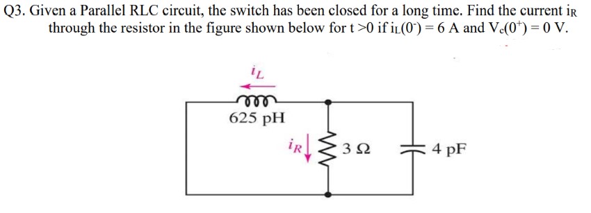

Transcribed Image Text:Q3. Given a Parallel RLC circuit, the switch has been closed for a long time. Find the current iR
through the resistor in the figure shown below for t>0 if iL(0) = 6 A and Vc(0*) = 0 V.
m
625 pH
302
4 pF
Expert Solution
This question has been solved!
Explore an expertly crafted, step-by-step solution for a thorough understanding of key concepts.

Step by stepSolved in 2 steps with 5 images

Knowledge Booster

Similar questions
- Question 3: Breadboard connections of a circuit are given in the figure below. 1- 2- GND .... ...... ...... 0.1µF 10mH 10mH 1kn a) Draw the schematic diagram of the circuit. b) Since we can observe the input signal with Channel 1 and the output signal with Channel 2, what does this circuit do? Write the type and purpose of the circuit. c) Plot the frequency versus transfer function by calculating the required frequencies. Channel 1+ Function generator Channel 2+arrow_forwardPlease answer in typing format I need it urgently I will like it please Please ASAP for the likearrow_forwardAn RTD forms one arm of a Wheatstone bridge, as shown in the figure below and the RTD is used to measure a constant temperature with the bridge operated in deflection mode. The bridge is balanced when the RTD temperature is at 0°C and the resistance R1 is set to 20 N. The RTD has a resistance of 20 2 at 0°C with an a = 0.0045°C-1. If the RTD is subjected to a temperature of 120°C and the output voltage from the bridge is 1.2 Volts, what is the input voltage? R₂ R₁ E₁ Hilllo R3 RTD RRTDarrow_forward
- Can you help me solve this and explain clearly I saw some answers on chegg but I don’t understand it .arrow_forwardA clipper circuit based on diodes are simple way to modify waveform in mechatronics. Assume that the two diodes shown in the circuit below are ideal diodes. If the input voltage in the circuit is a 1 kHz sinusoid with peak amplitude of 8V, sketch the Va.. (t) 10 kO 8V 10 kO Vin Vin(t) D2 Vout(t) RL Ims D1 6V -8V 4V Page | 1arrow_forwardIn the diagram below, the switch S has been closed for a long time. A) What is the output voltage Vout? What is the charge on the capacitor? b) The switch is opened, so the output voltage increases. What is the time constant that describes the charging of the capacitor in terms of R and C? c) When Vout reaches 10 V, the switch closes and the capacitor begins to discharge. What is the time constant that describes the discharging in terms of R and C? Hint: Apply Kirchhoff's Rules to both loops and the sum of the currents at the junction above the capacitor in the diagram, and use I=dq/dt. If the switch opens when Vout reaches a lower value, say 5V, the capacitor will charge again, and thus one can cycle the voltage with a time constant determined by the circuit: this demonstrates the principle of operation of an electronic timer. 4R S 15 V Vout Rarrow_forward
- 4- Design a boost converter that will have an output of 60 V from a 24-V source. Design for continuous inductor current and an output ripple voltage of less than one percent. The load is a resistance of 50 2. Assume ideal components for this design. VL ooooo ip - ^arrow_forwardNegative Clamping Circuit: Can you explain why the output voltage gets shifted down logically?arrow_forwardPlease try to understand the solution and try to answer in typing format please ASAP for the Plarrow_forward
- sel not i need clear ans by hand and solve very very fast in 20 min and thank you | DYBALA Describe and solve the following differential equation: y"-4y' + 3y = x²-2x+1arrow_forward3-2) Draw the circuit diagram to output F given in the expression above by referring to schematics for 2-2) and 2-3). Use the space below to draw both the IC with pin assignments and a circuit F schematic. Schematic diagram: IC diagram: +3V IND Cate che GNDarrow_forwardQ3) For the circuit shown in below, determine and sketch the output waveform for the give input signals: - Vini = 2 sin(wt) Vinz = 1 volt 100 k Ohm 50 k Ohm V out 50 k Ohm + V_in1 100 k Ohm V_in2arrow_forward
arrow_back_ios
SEE MORE QUESTIONS
arrow_forward_ios
Recommended textbooks for you
- Introductory Circuit Analysis (13th Edition)Electrical EngineeringISBN:9780133923605Author:Robert L. BoylestadPublisher:PEARSON
 Delmar's Standard Textbook Of ElectricityElectrical EngineeringISBN:9781337900348Author:Stephen L. HermanPublisher:Cengage Learning
 Programmable Logic ControllersElectrical EngineeringISBN:9780073373843Author:Frank D. PetruzellaPublisher:McGraw-Hill Education
  Fundamentals of Electric CircuitsElectrical EngineeringISBN:9780078028229Author:Charles K Alexander, Matthew SadikuPublisher:McGraw-Hill Education
 Electric Circuits. (11th Edition)Electrical EngineeringISBN:9780134746968Author:James W. Nilsson, Susan RiedelPublisher:PEARSON
 Engineering ElectromagneticsElectrical EngineeringISBN:9780078028151Author:Hayt, William H. (william Hart), Jr, BUCK, John A.Publisher:Mcgraw-hill Education,
Introductory Circuit Analysis (13th Edition)
Electrical Engineering
ISBN:9780133923605
Author:Robert L. Boylestad
Publisher:PEARSON
Delmar's Standard Textbook Of Electricity
Electrical Engineering
ISBN:9781337900348
Author:Stephen L. Herman
Publisher:Cengage Learning
Programmable Logic Controllers
Electrical Engineering
ISBN:9780073373843
Author:Frank D. Petruzella
Publisher:McGraw-Hill Education
Fundamentals of Electric Circuits
Electrical Engineering
ISBN:9780078028229
Author:Charles K Alexander, Matthew Sadiku
Publisher:McGraw-Hill Education
Electric Circuits. (11th Edition)
Electrical Engineering
ISBN:9780134746968
Author:James W. Nilsson, Susan Riedel
Publisher:PEARSON
Engineering Electromagnetics
Electrical Engineering
ISBN:9780078028151
Author:Hayt, William H. (william Hart), Jr, BUCK, John A.
Publisher:Mcgraw-hill Education,