Delmar's Standard Textbook Of Electricity
7th Edition
ISBN: 9781337900348
Author: Stephen L. Herman
Publisher: Cengage Learning
expand_more
expand_more
format_list_bulleted
Question

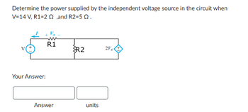
Transcribed Image Text:Determine the power supplied by the independent voltage source in the circuit when
V=14 V, R1=22,and R2=5 Q.
Your Answer:
R1
R2
21x
Answer
units
Expert Solution
This question has been solved!
Explore an expertly crafted, step-by-step solution for a thorough understanding of key concepts.
Step by stepSolved in 2 steps with 3 images

Knowledge Booster
Similar questions
- The figure shows a circuit. The switch S can be closed on either point A or C, but not both at the same time. Use the following quantities: V₁ = V₂ = 12 V R₁ = R4 = 1.00 R₂ = R3 = 2.00 [ R 4 O 2A O 6 A O 1 A O 12 A S О ЗА R₁ Determine the current through R₁ when the switch S is closed on A. W K Bm! Barrow_forwardDetermine the unknown. Rt, It, l1, l2, l3, V1, V2, V3, Py, & P3arrow_forwardPlease help me solve questions 1-5 using the given values found.arrow_forward
- Given n2 = 510, what is n₁? 5415° V 3060 85 1530 O 170 +21 000 ell n₁: N₂ + 30415° Varrow_forwardResistors Circuits I Each of the circuits below consists of a battery and several resistors. Several of the voltages, currents, and resistances are indicated. Use both of Kirchoff's Laws and Ohm's Law to determine as many of the other voltages, currents, and resistances as possible.arrow_forwardQuestion 2 4 for > 0 as shown in Figure 1 below. What is the energy? The independent current source in the circuit generates zero current for < 0 and a pulse of O a. g0r e Ob.30 e 20ke 2_-10t b.20,-10 c. 90re J 2--10tarrow_forward
- Given the following Resistances and Inductors in Series and Voltage Source: R1 - 40 ohms R2 = 61 ohms L1 = 1 Henry L2 = 9 Henry Vs = 383 Volts Frequency = 78 Hz What is the Amplitude of the voltage across R1?arrow_forward4.-For-labeled currents, draw an arrow to show the direction of the actual positive current. For labeled voltages, circle the node that is at the actual highest potential. Note that the positive and negative signs of the voltage represent the polarity of the probes of a voltmeter connected to the device. The value shown is the reading on the voltmeter. (segment of wire) 2A -2A -5A 2.de 3A TA Cov E 5V 12V + 3V -10V -201arrow_forwardI did a physics lab and got some values. I want to check them theoretically to see how the results differ. From this diagram, answer the following questions: The laws to be verified included the conservation of current in a node, the addition of potentials for components in series, and the addition of currents for components in parallel. The data : R1: 1094 ohm R2 : 998 ohm R3: 1094 ohmR4: 25 ohm Source 1 : 5 V Source 2 : 1.5 Varrow_forward
arrow_back_ios
SEE MORE QUESTIONS
arrow_forward_ios
Recommended textbooks for you
 Delmar's Standard Textbook Of ElectricityElectrical EngineeringISBN:9781337900348Author:Stephen L. HermanPublisher:Cengage Learning

Delmar's Standard Textbook Of Electricity
Electrical Engineering
ISBN:9781337900348
Author:Stephen L. Herman
Publisher:Cengage Learning