Oh no! Our experts couldn't answer your question.
Don't worry! We won't leave you hanging. Plus, we're giving you back one question for the inconvenience.
Submit your question and receive a step-by-step explanation from our experts in as fast as 30 minutes.
You have no more questions left.
Message from our expert:
It looks like you may have submitted a graded question that, per our Honor Code, experts cannot answer. We've credited a question to your account.
Your Question:

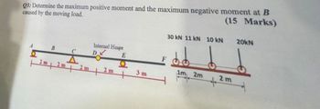
Transcribed Image Text:Q3: Determine the maximum positive moment and the maximum negative moment at B
caused by the moving load.
(15 Marks)
B
2m 2m
C
A
2 m
Internal Hinge
DV
2 m
E
3 m
30 kN 11 kN 10 kN
1m 2m
+
2m
20kN
Want to see the full answer?
Check out a sample Q&A hereKnowledge Booster
Learn more about
Need a deep-dive on the concept behind this application? Look no further. Learn more about this topic, mechanical-engineering and related others by exploring similar questions and additional content below.Similar questions
- Solve for the sum of moment of all forces clockwise direction is positive at point A, B, C & D. Include all moments. 2m Nool ad G= 8ON 100N-m 2m 75NM 2m R= 90N 2m P= 120N 2m 2m 2m 2m 2marrow_forwardDraw the FBD and show all the forces Calculate force for weight (W) gl=32.174 ft/s^2 Determine summation of forces in Y direction and X direction and set=0 Determine summation of moments with respect to point A and set=0arrow_forward3 For the beam shown, find the reactions at the supports and plot the shear-force and bending-moment diagrams. V = 9 kN, V2 = 9 kN, V3 = 200 mm, and V4 = 1100 mm. ATAT-V3 Provide values at all key points shown in the given shear-force and bending-moment diagrams. X (mm) B A = B = C = D = E= F= P = Q = E * KN * KN * KN × KN KN x KN ✩ kN.mm *kN.mm D 0.00 Reaction force R₁ (left) = In the shear-force and bending-moment diagrams given, +V 0.00 X (mm) 6.3 kN and reaction force R2 (right) = P 11.7 kN. Q 0.00arrow_forward
- The column shown is fabricated from two C250 x 30 standard steel shapes (see Appendix B for its cross-sectional properties) that are oriented back-to-back with a gap of 33 mm between the two channels. The column is fixed at its base and free to translate in the y direction at its upper end. Translation in the z direction, however, is restrained at its upper end. A load P is applied at an offset distance of 430 mm from the channel flanges. Use the AISC equations given in Section 16.5, and assume that L = 4.1 m, s = 33 mm, E = 200 GPa, oy = 275 MPa, and (Gallow); = 145 MPa. Offset - distance e P Lateral bracing in z direction C250 x 30 L C250 x 30 Cross section.arrow_forward18KN/M D 3m 5m 1-25 m EL = Constant B Draw Bending Moment diagram after you analyze the structure using the force Method. Redundant: vertical reaction and moment at B.arrow_forwardGot this wrong. please help and show work then round the final answer to 3 sig figs.arrow_forward
- 3arrow_forwardI can't seem to figure out the moment at C and D with the forces being F1=477lb F2=208lb F3=284 Can you help me figure out what I am missing here please?arrow_forwardThe shelf bracket is subjected to the force F = 336 Newtons at an angle 0 = 25.5°. Compute the moment (in N-m) that this force exerts about each of the two attachment points (screw locations in the figure). Take counterclockwise moments to be positive. a F 2013 cc CC Michael Swanbom BY NC SA Values for dimensions on the figure are given in the following table. Note the figure may not be to scale. Variable Value a 48.0 cm 45.6 cm 4.10 cm The moment about the upper attachment point is N-m. The moment about the lower attachment point is N-m. luk-arrow_forward
- SOLVE FOR THE SUM OF MOMENT OF ALL FORCES CLOCKWISE DIRECTION IS POSITIVE AT POINT A, B, C AND D. Nool =4 G= 80N 2m 2m R= 90N 2m P= 120N 2m 2m 2marrow_forwardPlease look at the images for details about the question. (For the second image, find out the correct values for A_x, A_y, and C_y)arrow_forwardfinal answers are Problem 1: ΣMA = 1371.93 lb-ft CCW Problem 2: By = 11,166 lb show the steps to get these answersarrow_forward
arrow_back_ios
SEE MORE QUESTIONS
arrow_forward_ios
Recommended textbooks for you
 Elements Of ElectromagneticsMechanical EngineeringISBN:9780190698614Author:Sadiku, Matthew N. O.Publisher:Oxford University Press
 Mechanics of Materials (10th Edition)Mechanical EngineeringISBN:9780134319650Author:Russell C. HibbelerPublisher:PEARSON
 Thermodynamics: An Engineering ApproachMechanical EngineeringISBN:9781259822674Author:Yunus A. Cengel Dr., Michael A. BolesPublisher:McGraw-Hill Education
 Control Systems EngineeringMechanical EngineeringISBN:9781118170519Author:Norman S. NisePublisher:WILEY
 Mechanics of Materials (MindTap Course List)Mechanical EngineeringISBN:9781337093347Author:Barry J. Goodno, James M. GerePublisher:Cengage Learning
 Engineering Mechanics: StaticsMechanical EngineeringISBN:9781118807330Author:James L. Meriam, L. G. Kraige, J. N. BoltonPublisher:WILEY

Elements Of Electromagnetics
Mechanical Engineering
ISBN:9780190698614
Author:Sadiku, Matthew N. O.
Publisher:Oxford University Press

Mechanics of Materials (10th Edition)
Mechanical Engineering
ISBN:9780134319650
Author:Russell C. Hibbeler
Publisher:PEARSON

Thermodynamics: An Engineering Approach
Mechanical Engineering
ISBN:9781259822674
Author:Yunus A. Cengel Dr., Michael A. Boles
Publisher:McGraw-Hill Education

Control Systems Engineering
Mechanical Engineering
ISBN:9781118170519
Author:Norman S. Nise
Publisher:WILEY

Mechanics of Materials (MindTap Course List)
Mechanical Engineering
ISBN:9781337093347
Author:Barry J. Goodno, James M. Gere
Publisher:Cengage Learning

Engineering Mechanics: Statics
Mechanical Engineering
ISBN:9781118807330
Author:James L. Meriam, L. G. Kraige, J. N. Bolton
Publisher:WILEY