Introductory Circuit Analysis (13th Edition)
13th Edition
ISBN: 9780133923605
Author: Robert L. Boylestad
Publisher: PEARSON
expand_more
expand_more
format_list_bulleted
Concept explainers
Question

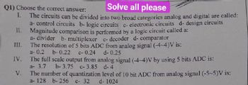
Transcribed Image Text:Q1) Choose the correct answer:
Solve all please
I.
The circuits can be divided into two broad categories analog and digital are called:
a-control circuits b- logic circuits c- electronic circuits d- design circuits
II. Magnitude comparison is performed by a logic circuit called a:
a- divider b- multiplexer c- decoder d- comparator
The resolution of 5 bits ADC from analog signal (-4-4)V is:
a- 0.2 b-0.22 c- 0.24
III.
IV.
V.
d- 0.25
The full scale output from analog signal (-4-4)V by using 5 bits ADC is:
a- 3.7
b-3.75 c-3.85 d-4
The number of quantization level of 10 bit ADC from analog signal (-5~5)V is:
a- 128 b- 256 c- 32
d-1024
Expert Solution
This question has been solved!
Explore an expertly crafted, step-by-step solution for a thorough understanding of key concepts.
Step by stepSolved in 6 steps

Knowledge Booster
Learn more about
Need a deep-dive on the concept behind this application? Look no further. Learn more about this topic, electrical-engineering and related others by exploring similar questions and additional content below.Similar questions
- 1-Write microprocessor program using mnemonics to add two numbers 08 and 06. 2-Write the object code of the program. 3-Perform the program using STEP function. 4-Execute the program and write the results. Object code Mnemonics MOV AX A1 B0 MOV AL B3 MOV BL 04 ADD AL F4 HLTarrow_forward2arrow_forwardBubbled AND Gate is A4 a) IC 7408 b) IC 7400 c) IC 7432 d) IC 7402arrow_forward
- 1. PLEASE EXPLAIN IN WRITING THE STEPS AND WHAT IS GOINING ONarrow_forwardA sensor needs a bias voltage of +3.000 volts. The DAC producing the voltage is 12 bits with a 3.3 volt reference. What is the DAC input code? 1241 3724 3103 3541arrow_forwardTwo same size PV Modules are connected in Parallel. The specification of each module is given as, Number of cells = 36, Area of each cell is 12 cm x 12 cm. Assume the necessary data. Refer to the above PV Panel choose the correct statement. a. The output current of each PV Module is 2.15A b. The output current of each PV Module is 8.6A c. The output current of each PV Module is 4.3A d. The output current of each PV Module is 1.25Aarrow_forward
- The analog to digital signal conversions involves two steps. What are they?arrow_forwardPart Carrow_forward16. What is the two's complement of 1011100111? 17. Explain function of each element in Figure 3. (Register A, B, C, Clock, Carry out,D, C, Q, PRE, S, CI, CO) Subtractor Circuit Register A Register C Register B PRE Carry Out (Sign Bit) CI CO Clock- Figure 3 18. In the Figure 4, Register A is 1011 and Register B is 0010. a. What are the contents of register C after 2 clock pulses? b. What is the output of flip flop (Q) after the second clock pulse? c. What is the output of flip flop (Q) after the third clock pulse? d. What are the contents of register C after 5 clock pulses? Adder Circuit Register A Register C Register B B CLR CI CO Q Clock Figure 4 19. The serial adder required ten clock pulses to add two, five bit binary numbers. (True or false. İf it is false write correct one .) 8.arrow_forward
- A potentiometer with rotation limited only to 300 degree configured as a voltage divider with 5V supply. The output of this circuit is fed to ADC that converts the analog value of 0 to 5V to digital 10 bits of 0 to 1023. If the potentiometer rotates by 175 degrees, what is the data read in the ADC converter. Select one: a. 1001010101 O b. 1010110101 c. 1100010100 O d. 1001101100 e. 1101100100 O f. 1000111010 O g. 0101111001 Oh. 0111010011arrow_forward4. The following Data input and data select waveforms are applied to a Multiplexer. Determine the output waveform. Do D Dy Soarrow_forwardScimal value of the value that will occur at the ADC output. (ADC is 12 Question 2 MN is the last two g160100555 - yu digits of In an analog measurement operation set as an external reference, the reference source of the ADC is a voltage source of 5 analog input, write the g160100555-Gu Aumber your student 010055 g160100555 - Yu 9441 20100 g160100555- Y 44 s0100538 g160100555 - Y 944 201005 g160100 2447 .5Volts. In case of 3.5V voltage to the 30100555 -98 9447 30100555 - 987 30100555arrow_forward
arrow_back_ios
SEE MORE QUESTIONS
arrow_forward_ios
Recommended textbooks for you
 Introductory Circuit Analysis (13th Edition)Electrical EngineeringISBN:9780133923605Author:Robert L. BoylestadPublisher:PEARSON
 Delmar's Standard Textbook Of ElectricityElectrical EngineeringISBN:9781337900348Author:Stephen L. HermanPublisher:Cengage Learning
 Programmable Logic ControllersElectrical EngineeringISBN:9780073373843Author:Frank D. PetruzellaPublisher:McGraw-Hill Education
 Fundamentals of Electric CircuitsElectrical EngineeringISBN:9780078028229Author:Charles K Alexander, Matthew SadikuPublisher:McGraw-Hill Education
 Electric Circuits. (11th Edition)Electrical EngineeringISBN:9780134746968Author:James W. Nilsson, Susan RiedelPublisher:PEARSON
 Engineering ElectromagneticsElectrical EngineeringISBN:9780078028151Author:Hayt, William H. (william Hart), Jr, BUCK, John A.Publisher:Mcgraw-hill Education,

Introductory Circuit Analysis (13th Edition)
Electrical Engineering
ISBN:9780133923605
Author:Robert L. Boylestad
Publisher:PEARSON

Delmar's Standard Textbook Of Electricity
Electrical Engineering
ISBN:9781337900348
Author:Stephen L. Herman
Publisher:Cengage Learning

Programmable Logic Controllers
Electrical Engineering
ISBN:9780073373843
Author:Frank D. Petruzella
Publisher:McGraw-Hill Education

Fundamentals of Electric Circuits
Electrical Engineering
ISBN:9780078028229
Author:Charles K Alexander, Matthew Sadiku
Publisher:McGraw-Hill Education

Electric Circuits. (11th Edition)
Electrical Engineering
ISBN:9780134746968
Author:James W. Nilsson, Susan Riedel
Publisher:PEARSON

Engineering Electromagnetics
Electrical Engineering
ISBN:9780078028151
Author:Hayt, William H. (william Hart), Jr, BUCK, John A.
Publisher:Mcgraw-hill Education,