
Mechanics of Materials (MindTap Course List)
9th Edition
ISBN: 9781337093347
Author: Barry J. Goodno, James M. Gere
Publisher: Cengage Learning
expand_more
expand_more
format_list_bulleted
Related questions
Question
m=400mm
n=300mm
q=28mm
r=20mm
P=0.9kN
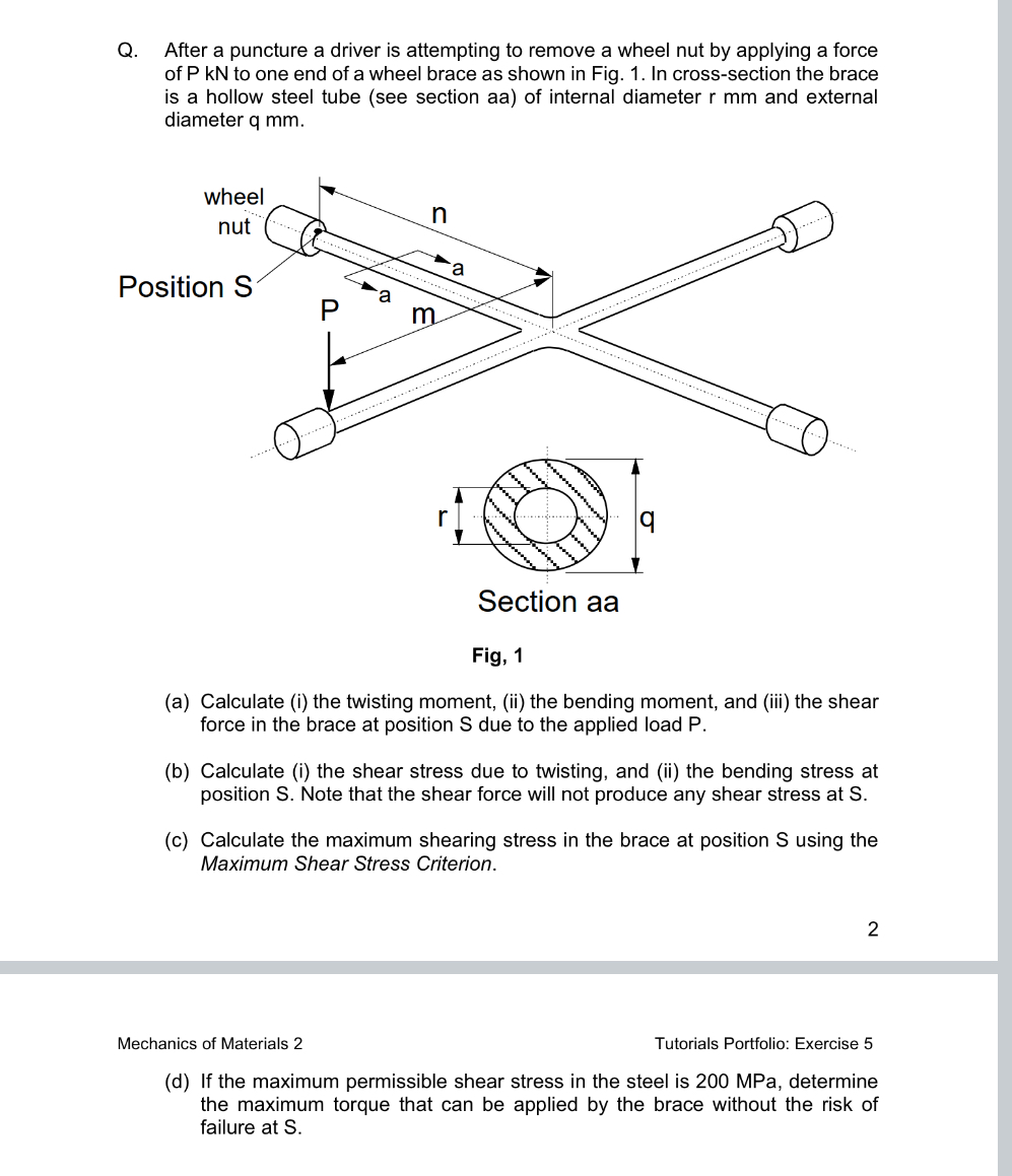

Transcribed Image Text:Q. After a puncture a driver is attempting to remove a wheel nut by applying a force
of P KN to one end of a wheel brace as shown in Fig. 1. In cross-section the brace
is a hollow steel tube (see section aa) of internal diameter r mm and external
diameter q mm.
wheel
nut
n
Position S
P
m
a
r
9
Section aa
Fig, 1
(a) Calculate (i) the twisting moment, (ii) the bending moment, and (iii) the shear
force in the brace at position S due to the applied load P.
(b) Calculate (i) the shear stress due to twisting, and (ii) the bending stress at
position S. Note that the shear force will not produce any shear stress at S.
(c) Calculate the maximum shearing stress in the brace at position S using the
Maximum Shear Stress Criterion.
2
Mechanics of Materials 2
Tutorials Portfolio: Exercise 5
(d) If the maximum permissible shear stress in the steel is 200 MPa, determine
the maximum torque that can be applied by the brace without the risk of
failure at S.
Expert Solution
This question has been solved!
Explore an expertly crafted, step-by-step solution for a thorough understanding of key concepts.

Step by stepSolved in 2 steps with 3 images

Knowledge Booster

Similar questions
- Compare the angle of twist 1 for a thin-walled circular tube (see figure) calculated from the approximate theory for thin-walled bars with the angle of twist 2 calculated from the exact theory of torsion for circular bars, Express the ratio 12terms of the non-dimensional ratio ß = r/t. Calculate the ratio of angles of twist for ß = 5, 10, and 20. What conclusion about the accuracy of the approximate theory do you draw from these results?arrow_forward.17 A mountain-bike rider going uphill applies torque T = Fd(F = l5lb, d = 4 in.) to the end of the handlebars ABCD by pulling on the handlebar extenders DE. Consider the right half of the handlebar assembly only (assume the bars are fixed at the fork at A). Segments AB and CD are prismatic with lengths L, = 2 in.andL3 = 8.5 in, and with outer diameters and thicknesses d01 = 1.25 in. 101 = 0.125 in. and d03 = O.87in.,i03 = 0.ll5in, respectively as shown. Segment BC’ of length L, = 1.2 in. however. is tapered, and outer diameter and thickness vary linearly between dimensions at B and C. Consider torsion effects only. Assume G = 4000 ksi is constant. Derive an integral expression for the angle of twist of half of the handlebar tube when it is subjected to torque T = Fd acting at the end. Evaluate ‘b1-, for the given numerical1ues.arrow_forwardA seesaw weighing 3 lb/ft of length is occupied by two children, each weighing 90 lb (see figure). The center of gravity of each child is 8 ft from the fulcrum. The board is 19 ft long, 8 in. wide, and 1.5 in. thick. What is the maximum bending stress in the board?arrow_forward
- A sign of weight W is supported at its base by four bolls anchored in a concrete footing. Wind pressure P acts normal to the surface of the sign; the resultant of the uniform wind pressure is force fat the center of pressure (C.P). The wind force is assumed to create equal shear forces F/4 in the y direction at each boll (see figure parts a and c). The overturning effect of the wind force also causes an uplift force R at bolts A and C and a downward force (— R) al bolts B and D (see figure part b). The resulting effects of the wind and the associated ultimate stresses for each stress condition are normal stress in each boll (h — 60 ksi); shear through the base plate (th = 17 ksi); horizontal shear and bearing on each bolt ( tfur = 25 ksi and cr^ = 75 ksi): and bearing on the bottom washer at B (or D) (abor = 50 ksi).arrow_forwardRepeat Problem 11.2-3 assuming that R= 10 kN · m/rad and L = 2 m.arrow_forwardValues are m= 360mm n= 375mm q= 24mm r= 18mm P= 0.6kNarrow_forward
- A link of a valve gear has to be curved in one plane, for the sake of clearance. Estimate the maximum tensile and compressive stress in the link if the thrust is 2500 N. (Cam bridge) ANSWER: maximum tensile 38.0 MN/m2; maximum compressive 46.0 MNIm2. Please show the solution to get the answer.arrow_forwardFor the simply supported beam subjected to the loading shown, derive equations for the shear force V and the bending moment M for any location in the beam. (Place the origin at point A.) Let a-3.25 m, b=4.75 m, Pg - 35kN, and Pc = 80kN. Construct the shear- force and bending-moment diagrams on paper and use the results to answer the questions in the subsequent parts of this GO exercise. A Ay- 58.66 - Dy- Calculate the reaction forces A, and Dy acting on the beam. Positive values for the reactions are indicated by the directions of the red arrows shown on the free-body diagram below. (Note: Since Ax = 0, it has been omitted from the free-body diagram.) Answers: a 56.33 (a) V= (b) V- (c) V- B i i PB B kN с kN C Determine the shear force acting at each of the following locations: (a) x-2m (b)x - 4 m (c) x-8 m Note that x = 0 at support A. When entering your answers, use the shear-force sign convention detailed in Section 7.2. 3 3 3 KN D b kN D ·x Dyarrow_forwardA 4-cm-OD, 3-cm-ID, circular shaft supports a 200 N load and is supported at two points, which are 2-m apart as shown here. What is the radius of curvature of the bending shaft when it is made of a material whose modulus of elasticity is 50 GPa? Multiple Choice O O O O 1087 m 5 m 432 m 65 marrow_forward
- A solid cantilevered aluminum alloy rod, 10-mm in diameter, supports a Parol (Christmas Lantern). The hanging Parol subjects the rod to a bending moment of 10.2 Nm along the x-axis, as well as Torque (T) at its fixed end (Section B). If the yield strength oYield in tension of the aluminum alloy is 103.9 MPa at point n of Section B, what is the maximum torque the rod can carry under the maximum distortion-energy theory (MDET)? L aluminum rod Figure 1A Y B cross-section of the rod Figure 1B Image is from Parol clipart 2 Clipart Stationarrow_forwardParrow_forwardCould someone show me how to this this problem? Thank you in advance!arrow_forward
arrow_back_ios
SEE MORE QUESTIONS
arrow_forward_ios
Recommended textbooks for you
- Mechanics of Materials (MindTap Course List)Mechanical EngineeringISBN:9781337093347Author:Barry J. Goodno, James M. GerePublisher:Cengage Learning
Mechanics of Materials (MindTap Course List)
Mechanical Engineering
ISBN:9781337093347
Author:Barry J. Goodno, James M. Gere
Publisher:Cengage Learning