
Elements Of Electromagnetics
7th Edition
ISBN: 9780190698614
Author: Sadiku, Matthew N. O.
Publisher: Oxford University Press
expand_more
expand_more
format_list_bulleted
Related questions
Question

Transcribed Image Text:: +♡
العنوان
X=
C
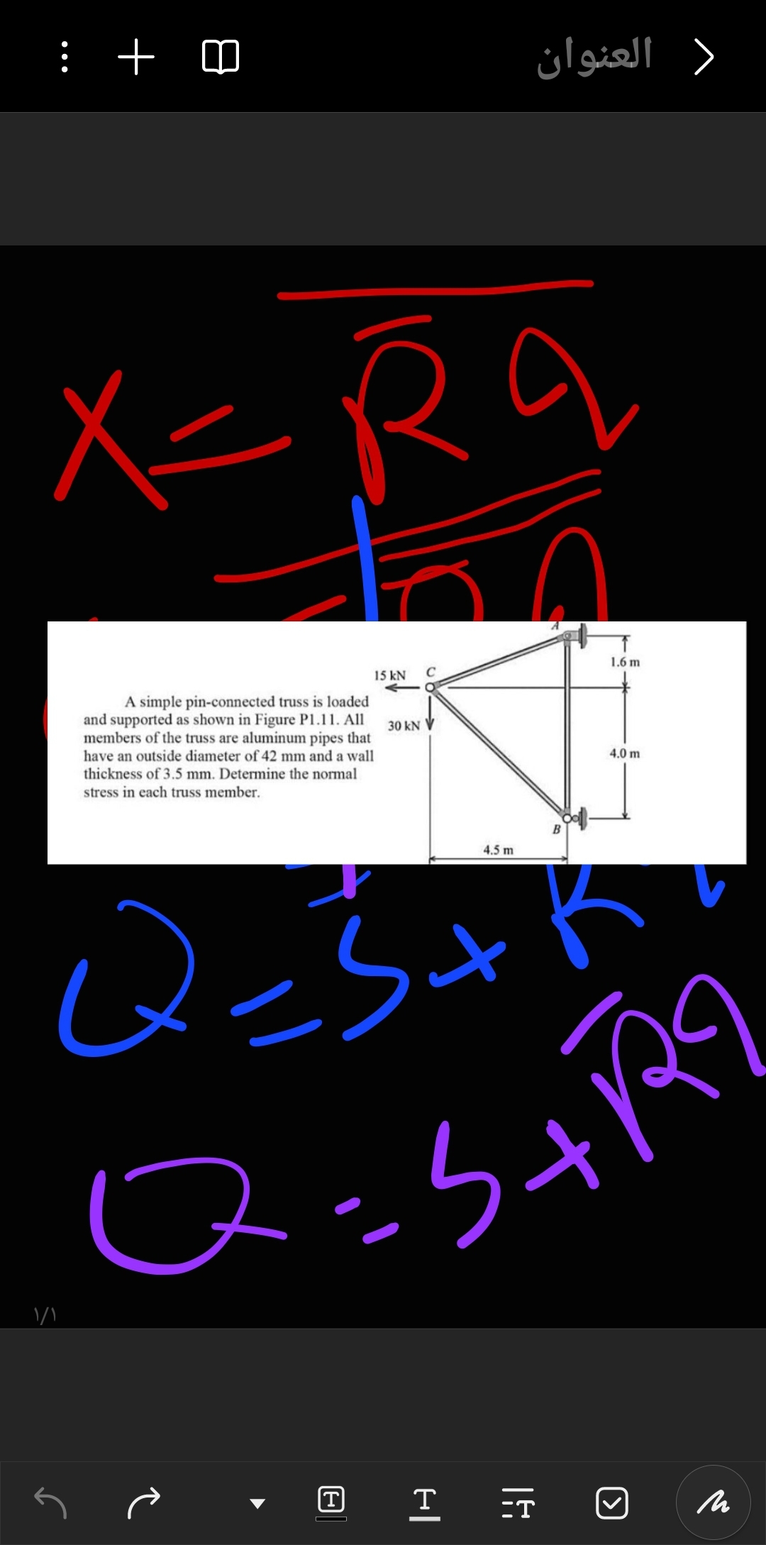
15 kN
C
1.6 m
A simple pin-connected truss is loaded
and supported as shown in Figure P1.11. All
members of the truss are aluminum pipes that
have an outside diameter of 42 mm and a wall
thickness of 3.5 mm. Determine the normal
stress in each truss member.
30 kN
4.0 m
>
۱/۱
Q=5+
4.5 m
Q=S+R9
T
Τ
M
Expert Solution
This question has been solved!
Explore an expertly crafted, step-by-step solution for a thorough understanding of key concepts.

Step by stepSolved in 2 steps with 2 images

Knowledge Booster

Similar questions
- Please write it out. I don’t like the computer typed answers. Need help on all questions. Please include all units, steps to the problem and information such as its direction or if it is in compression or tension. Thx.arrow_forwardPlease answer the problem completely. Show a free body diagram. Final answers: 1st section: 166.67 mPa 2nd Section: 55.56 mPa 3rd Section: 122.22 mPaarrow_forwardSolve the problem shown below. Each answer is worth equal credit. Show all necessary steps of your work clearly to obtain credit. Final answer must be to 3 significant figures and contain units and be in the box. Using P1= 6.0 kips, then determine the reactions and member forces of the truss. a) List reactions at A and K? (Use positive, +, to indicate a reaction that is up, to the right, and counterclockwise.) [30 pts] RAX: RAY: Rkx: Rky: b) Determine the member forces using either the method of joints or method of sections. (Include Units and the correct sign in the answer, (Use: '+'= tension, & '-' = compression) J I H G 4 ft K A -3 ft- B P1 -3 ft- C P1 -3 ft D P1 E -3 ft 3 ft- P1 P1 F FBC: FCJ: FI: FEG: FDH: FIC:arrow_forward
- Problem 7.34 Consider the two-member frame shown in (Figure 1) Suppose that w = 2.6 kN/m, w = 1.9 kN/m Follow the sign convention. Figure -1.5m -1.5m 15m 1.5m 1 of 1 Part A Determine the normal force at point E. Express your answer to three significant figures and include the appropriate units. NE- Value Submit Previous Answers Request Answer Incorrect; Try Again; 4 attempts remaining Part B Determine the shear force at point E Express your answer to three significant figures and include the appropriate units. VE = Part C HA Value Mg Value Submit Units Heavest Answ Determine the magnitude of the moment at point E. Express your answer to three significant figures and include the appropriate units. < Return to Assignment Units Pearson ? Units Provide Feedback 16 O ? 6 of 6 Revisearrow_forwardI need DE,DF,GFarrow_forwardI need to find the forces in each tube but I keep getting stuck. I have been getting really long equations to do algibra onwhich I suspect might be where the error was comming from. The values I have tried are F2 = -0.97786, and -4.889 kipsarrow_forward
- Q1: A steel pipe column with outside diameter 0.5 in and its wall thickness 0,25 in. supports a load of 4.45 kN. The steel pipe rests on a square steel base plate, this base plate is resting on a concrete slab as illustrated in the attached figure. 1-Determine the bearing stress between the stcel pipe and the stecl plate. 2-If the bearing stress of the steel plate on the concrete slab must be limited to 90 nci what is the minimum allowable plate dimension (a)? 3-Determine the average shear stress in the steel plate, explain? Load Outside diameter - 6.5S in. Wall thickness - 0.25 in. Square steel- base plate Concrete slabarrow_forwardH6.arrow_forwardtrussarrow_forward
- A 90 degree “reducing elbow” is a common pipe fitting used in industry and agriculturalapplications. Consider an illustration of one below to answer the following:(b) What are the retaining forces, Fx and Fy, needed to keep the pipe in place if P2 is 1.25 bar fx should be 5495 N and fy should be 773 Narrow_forwardarrow_forwardAfter an unfortunate accident occurred at a local warehouse, you were contracted to determine the cause. A jib crane collapsed and injured a worker. An image of this type of crane is shown in the figure.The horizontal steel beam had a mass of 81.70 kg per meter of length, and the tension in the cable was T-11260 N. The crane was rated for a maximum load of 500 kg. If d 5.000 m. s-0.486 m, z- 1.600 m. and h= 1.890 m, what was the magnitude of W₁ (the load on the crane) before the collapse? The acceleration due to gravity is g 9.810 m/s². = WL What was the magnitude of force Fp at the attachment point P? Fp= N W₁arrow_forward
arrow_back_ios
SEE MORE QUESTIONS
arrow_forward_ios
Recommended textbooks for you
- Elements Of ElectromagneticsMechanical EngineeringISBN:9780190698614Author:Sadiku, Matthew N. O.Publisher:Oxford University Press
 Mechanics of Materials (10th Edition)Mechanical EngineeringISBN:9780134319650Author:Russell C. HibbelerPublisher:PEARSON
 Thermodynamics: An Engineering ApproachMechanical EngineeringISBN:9781259822674Author:Yunus A. Cengel Dr., Michael A. BolesPublisher:McGraw-Hill Education
  Control Systems EngineeringMechanical EngineeringISBN:9781118170519Author:Norman S. NisePublisher:WILEY
 Mechanics of Materials (MindTap Course List)Mechanical EngineeringISBN:9781337093347Author:Barry J. Goodno, James M. GerePublisher:Cengage Learning
 Engineering Mechanics: StaticsMechanical EngineeringISBN:9781118807330Author:James L. Meriam, L. G. Kraige, J. N. BoltonPublisher:WILEY
Elements Of Electromagnetics
Mechanical Engineering
ISBN:9780190698614
Author:Sadiku, Matthew N. O.
Publisher:Oxford University Press
Mechanics of Materials (10th Edition)
Mechanical Engineering
ISBN:9780134319650
Author:Russell C. Hibbeler
Publisher:PEARSON
Thermodynamics: An Engineering Approach
Mechanical Engineering
ISBN:9781259822674
Author:Yunus A. Cengel Dr., Michael A. Boles
Publisher:McGraw-Hill Education
Control Systems Engineering
Mechanical Engineering
ISBN:9781118170519
Author:Norman S. Nise
Publisher:WILEY
Mechanics of Materials (MindTap Course List)
Mechanical Engineering
ISBN:9781337093347
Author:Barry J. Goodno, James M. Gere
Publisher:Cengage Learning
Engineering Mechanics: Statics
Mechanical Engineering
ISBN:9781118807330
Author:James L. Meriam, L. G. Kraige, J. N. Bolton
Publisher:WILEY