Introductory Circuit Analysis (13th Edition)
13th Edition
ISBN: 9780133923605
Author: Robert L. Boylestad
Publisher: PEARSON
expand_more
expand_more
format_list_bulleted
Question
thumb_up100%
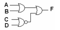
Question : see the attached picture
- Please write a logical function for the following circuit and then construct a truth table.
- Implement the circuit using only the minimum possible IC SN74LS00.
- Check that your table matches the output of the circuit you created.

Transcribed Image Text:A
B-
D
Expert Solution
This question has been solved!
Explore an expertly crafted, step-by-step solution for a thorough understanding of key concepts.
Step by stepSolved in 2 steps with 2 images

Knowledge Booster
Learn more about
Need a deep-dive on the concept behind this application? Look no further. Learn more about this topic, electrical-engineering and related others by exploring similar questions and additional content below.Similar questions
- 4. Use the Word table tool to construct the truth table for this circuit. Be sure to include intermediate values. Insert column headings in the first row. Be sure to use the Insert > Equation tool so that standard Boolean logic symbols are displayed in the headings. A B. D In the circuit implementation of an 8-bit adder, explain why the carry bit connection of the least- significant bit is connected to ground. Explain in words what values for A, B, C, D, E will cause a 1 to appear at point X. A B Earrow_forwardHi I need help to understand the boolean Expression. And thank youarrow_forward#7. A,b,carrow_forward
- At a local car dealership, there are 4 security cameras. There is a screen in the security office to view the cameras according to the following rules: Each camera can be viewed on a sreen in the security office, but only one at a time. The security guard must insert his key to view the screen. Otherwise the screen is left blank. Using a 4x1 mux, draw a logic circuit that implements the behavior of this block. (There is no diagram or image for this question.)arrow_forwardThis is a logic gate simplification with certain laws to be followed. Please read the instructions on the given image, I will like your answer if you answered it properly and accurately. Thank you in advancearrow_forwardplease solve number 3arrow_forward
- ---CIRCUITS TO BOOLEAN FORMULAS--- Write a Boolean formula for the following circuit:arrow_forwardBuild the circuit of the Boolean expression using ICs. If it’s not possible. Draw an approximate diagram of the circlearrow_forwardConsider the following circuit D3 D2 D1 DO In no more than 50 words total, answer the following. What commonly used digital logic component does this circuit implement. What purpose might this circuit serve in a computer system? Out1 Outoarrow_forward
- For the circuit shown, a closed switch is represented by a logic 1, and an open switch by a logic 0. If v =5 V across the resistor R is represented by a logic 1, and v = 0 V bya logic 0, then what Boolean expression of the state of the switches best describes the voltage across the resistor? W + 5 V OR= X (Y +W) OR=WXY OR=W+ X +Y OR=XY +WX+ WYarrow_forwarddesign a combinational circuit with three inputs and one output. the output is 1 when the binary value of the inputs is greater than decimal equivalent 4. The output is 0 otherwise. Write the truth table, k map,expression and circuitarrow_forwardCreate a circuit to generate odd parity bit for a 3-bit code. a. Construct the truth table. b. Use K-map to simplify the circuit. c. Draw the circuit with minimum number of gates. (I did the question myself, but I'm confused as to why the K-map does not provide the simplified circuit to build the minimum number of gates)arrow_forward
arrow_back_ios
arrow_forward_ios
Recommended textbooks for you
 Introductory Circuit Analysis (13th Edition)Electrical EngineeringISBN:9780133923605Author:Robert L. BoylestadPublisher:PEARSON
 Delmar's Standard Textbook Of ElectricityElectrical EngineeringISBN:9781337900348Author:Stephen L. HermanPublisher:Cengage Learning
 Programmable Logic ControllersElectrical EngineeringISBN:9780073373843Author:Frank D. PetruzellaPublisher:McGraw-Hill Education
 Fundamentals of Electric CircuitsElectrical EngineeringISBN:9780078028229Author:Charles K Alexander, Matthew SadikuPublisher:McGraw-Hill Education
 Electric Circuits. (11th Edition)Electrical EngineeringISBN:9780134746968Author:James W. Nilsson, Susan RiedelPublisher:PEARSON
 Engineering ElectromagneticsElectrical EngineeringISBN:9780078028151Author:Hayt, William H. (william Hart), Jr, BUCK, John A.Publisher:Mcgraw-hill Education,

Introductory Circuit Analysis (13th Edition)
Electrical Engineering
ISBN:9780133923605
Author:Robert L. Boylestad
Publisher:PEARSON

Delmar's Standard Textbook Of Electricity
Electrical Engineering
ISBN:9781337900348
Author:Stephen L. Herman
Publisher:Cengage Learning

Programmable Logic Controllers
Electrical Engineering
ISBN:9780073373843
Author:Frank D. Petruzella
Publisher:McGraw-Hill Education

Fundamentals of Electric Circuits
Electrical Engineering
ISBN:9780078028229
Author:Charles K Alexander, Matthew Sadiku
Publisher:McGraw-Hill Education

Electric Circuits. (11th Edition)
Electrical Engineering
ISBN:9780134746968
Author:James W. Nilsson, Susan Riedel
Publisher:PEARSON

Engineering Electromagnetics
Electrical Engineering
ISBN:9780078028151
Author:Hayt, William H. (william Hart), Jr, BUCK, John A.
Publisher:Mcgraw-hill Education,