
Introductory Circuit Analysis (13th Edition)
13th Edition
ISBN: 9780133923605
Author: Robert L. Boylestad
Publisher: PEARSON
expand_more
expand_more
format_list_bulleted
Related questions
Question
thumb_up100%
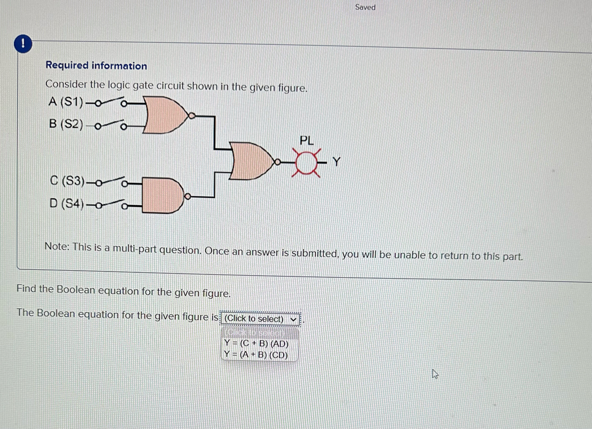

Transcribed Image Text:Required information
Consider the logic gate circuit shown in the given figure.
A (S1)-0
B (S2)
C (S3)-0- O
D (S4)-o
Find the Boolean equation for the given figure.
The Boolean equation for the given figure is (Click to select)
PL
Note: This is a multi-part question. Once an answer is submitted, you will be unable to return to this part.
Y = (C+B) (AD)
Y = (A + B) (CD)
Saved
h
Expert Solution
This question has been solved!
Explore an expertly crafted, step-by-step solution for a thorough understanding of key concepts.

This is a popular solution

Trending nowThis is a popular solution!

Step by stepSolved in 2 steps with 2 images

Knowledge Booster


Learn more about
Need a deep-dive on the concept behind this application? Look no further. Learn more about this topic, electrical-engineering and related others by exploring similar questions and additional content below.Similar questions
- Consider the circuit below. The switches are controlled by logic variables such that, if A is high, switch A is closed, and if A is low, switch A is open. Conversely, if B is high, the switch labeled is open, and if B is low, the switch labeled is closed. The output variable is high if the output voltage is 5V, and the output variable is low if the output voltage is zero. a. Write a logic expression for the output variable. b. Construct the truth table for the circuit. A Logic 1 5V(+ B C Logic 0 Rarrow_forward(a) A logic circuit shown in Figure Q.3 has a 4-bit input A and B, three 4-bit wide 2:1 muxes, a 4-bit adder, a 4-bit output F, and a carry flag C. For the given Table Q.3, fill in the value of output F and carry flag C for the given value of A, B, S0, S1 and S2. 51 52 1001 Flag C 0011 Figure Q.3 Table Q.3 A So S1 S2 F Flag C 0001 1000 0010 1001 1 1 0011 1101 0100 1101 1110 0111 1arrow_forwardDesign a combinational circuit using multiplexer for a car chime based on thefollowing system: A car chime or bell will sound if the output of the logic circuit(X) is set to a logic ‘1’. The chime is to be sounded for either of the followingconditions:• if the headlights are left on when the engine is turned off and• if the engine is off and the key is in the ignition when the door is opened.Use the following input names and nomenclature in the design process:• ‘E’ – Engine. ‘1’ if the engine is ON and ‘0’ if the engine is OFF• ‘L’ – Lights. ‘1’ if the lights are ON and ‘0’ if the lights are OFF• ‘K’ – Key. ‘1’ if the key is in the ignition and ‘0’ if the key is not in the ignition• ‘D’ – Door. ‘1’ the door is open and ‘0’ if the door is closed• ‘X’ – Output to Chime. ‘1’ is chime is ON and ‘0’ if chime is OFFarrow_forward
- hi, i have a problem with this logic gate question. can you please help me.arrow_forwardDesign the following combinational logic circuit with a four-bit input and a three-bit output. The input represents two unsigned 2-bit numbers: A1 A0 and B1 B0. The output C2 C1.C0 is the result of the integer binary division A1 A0/B1 B0 rounded down to three bits. The 3-bit output has a 2-bit unsigned whole part C2 C1 and a fraction part CO. The weight of the fraction bit CO is 21. Note the quotient should be rounded down, i.e. the division 01/11 should give the outputs 00.0 (1/3 rounded down to 0) not 00.1 (1/3 rounded up to 0.5). A result of infinity should be represented as 11.1. A minimal logic implementation is not required. (Hint: start by producing a truth table of your design).arrow_forwardQuestion 6a and b are: Draw the logic diagram for the following Boolean expression. Then simplify the Boolean expression in (a) using a karnaugh map. The picture goes into more details about the assignment.arrow_forward
- 9 Part 1 of 2 Mc Graw Hill Required information Consider the logic gate circuit shown in the given figure. A (S1)-0- B (S2)-0 C (S3)-0- AB B BC B+C What is the Boolean equation for the given figure? ***************** The Boolean equation for the given figure is (Click to select) Note: This is a multi-part question. Once an answer is submitted, you will be unable to return to this part.arrow_forwardLOGIC GATE ( NEED ONLY HANDWRITTEN SOLUTION PLEASE OTHERWISE DOWNVOTE).arrow_forwardPLease Explain the design process of this thoroughlyarrow_forward
- What logic function is performed by this circuit? VDD a. O d. e. A b. None OC AB AB A+B A+B O f. B AB M₁ M₂ M3 M4 F M5arrow_forwardCreate a circuit to generate odd parity bit for a 3-bit code. a. Construct the truth table. b. Use K-map to simplify the circuit. c. Draw the circuit with minimum number of gates. (I did the question myself, but I'm confused as to why the K-map does not provide the simplified circuit to build the minimum number of gates)arrow_forwardCan the expert draw a full adder gate?arrow_forward
arrow_back_ios
SEE MORE QUESTIONS
arrow_forward_ios
Recommended textbooks for you
- Introductory Circuit Analysis (13th Edition)Electrical EngineeringISBN:9780133923605Author:Robert L. BoylestadPublisher:PEARSON
 Delmar's Standard Textbook Of ElectricityElectrical EngineeringISBN:9781337900348Author:Stephen L. HermanPublisher:Cengage Learning
 Programmable Logic ControllersElectrical EngineeringISBN:9780073373843Author:Frank D. PetruzellaPublisher:McGraw-Hill Education
  Fundamentals of Electric CircuitsElectrical EngineeringISBN:9780078028229Author:Charles K Alexander, Matthew SadikuPublisher:McGraw-Hill Education
 Electric Circuits. (11th Edition)Electrical EngineeringISBN:9780134746968Author:James W. Nilsson, Susan RiedelPublisher:PEARSON
 Engineering ElectromagneticsElectrical EngineeringISBN:9780078028151Author:Hayt, William H. (william Hart), Jr, BUCK, John A.Publisher:Mcgraw-hill Education,
Introductory Circuit Analysis (13th Edition)
Electrical Engineering
ISBN:9780133923605
Author:Robert L. Boylestad
Publisher:PEARSON
Delmar's Standard Textbook Of Electricity
Electrical Engineering
ISBN:9781337900348
Author:Stephen L. Herman
Publisher:Cengage Learning
Programmable Logic Controllers
Electrical Engineering
ISBN:9780073373843
Author:Frank D. Petruzella
Publisher:McGraw-Hill Education
Fundamentals of Electric Circuits
Electrical Engineering
ISBN:9780078028229
Author:Charles K Alexander, Matthew Sadiku
Publisher:McGraw-Hill Education
Electric Circuits. (11th Edition)
Electrical Engineering
ISBN:9780134746968
Author:James W. Nilsson, Susan Riedel
Publisher:PEARSON
Engineering Electromagnetics
Electrical Engineering
ISBN:9780078028151
Author:Hayt, William H. (william Hart), Jr, BUCK, John A.
Publisher:Mcgraw-hill Education,