Introductory Circuit Analysis (13th Edition)
13th Edition
ISBN: 9780133923605
Author: Robert L. Boylestad
Publisher: PEARSON
expand_more
expand_more
format_list_bulleted
Question
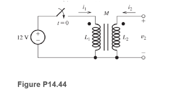
Consider the circuit shown in Figure P14.44. The two coils have L1=0.1 H, L2=10 H, and M=1 H. Prior to t=0, the currents in the coils are zero. At t=0, the switch closes. Determine and sketch i1(t) and v2(t) to scale versus time

Transcribed Image Text:м
1=0
12 V
Figure P14.44
Expert Solution
This question has been solved!
Explore an expertly crafted, step-by-step solution for a thorough understanding of key concepts.
This is a popular solution
Trending nowThis is a popular solution!
Step by stepSolved in 4 steps with 2 images

Knowledge Booster
Learn more about
Need a deep-dive on the concept behind this application? Look no further. Learn more about this topic, electrical-engineering and related others by exploring similar questions and additional content below.Similar questions
- Q2. a) (i) For current measurement applications, derive an expression for the open circuit voltage developed across the terminals of a Rogowski coil. Assume that the coil has a radius, R, and N turns of radius, r. Use a suitable drawing to indicate the various quantities/variables used in your equations. (ii) Explain briefly how you change this Rogowski coil into a current transformer.arrow_forwardYou have developed an idea for using a poly Si surface‐ micromachined cantilever. Initially, you designed a process flow for creating this simple structure, and the process flow is detailed in the figure below. ( cross section view and top view)There are several critical errors with this process (things that won’t work or won’t produce the result). Please find the critical errors in this process flow and, where possible, suggest alternate approaches. Do not worry about the accumulation of errors, but rather treat each step assuming that the structure up to that step could be created.This structure is actually quite simple to make. Develop a simpler process flow and associated masks to create the final structure. Be sure to show cross‐sectional and planar views of all key steps in the process.arrow_forwardConsider the circuit shown in Figure P14.36. The two coils have L1=0.1 H, L2=10 H, and M=0.5 H. Prior to t=0, the currents in the coils are zero. At t=0, the switch closes. Determine and sketch i1(t) and i2(t) to scale versus time.arrow_forward
- 4. Which of the following is a mathematically incorrect operation and why? a) gradient of a divergence b) curl of a gradient c) gradient of a curl d) divergence of a curlarrow_forward20 What is countertorque a measure of? PRACTICAL APPLICATIONS ou are working as an electrician in a large steel manufacturing plant, and Y in the of doing preventive maintenance on a large DC you are generator. You have megged both the series and shunt field windings and found that each has over 10 M2 to ground. Your ohmmeter, however, indicates a resistance of 1.5 2 across terminals S, and S,. The ohmmeter indicates a resistance of 225 N between terminals F, and F2. Are these readings normal for this type machine, or is there a likely problem? Explain your answer. processarrow_forwardPlease solve it with proper explanationarrow_forward
- A sinusoidal voltage has a value of 100 volts at 2.5 milliseconds and takes 20 milliseconds to complete one cycle. Then find the maximum cost and the time to reach it for the first time.arrow_forward(B)-Explain by drawing the change in the direction of current flows through coils at the ideal case of commutation by considering coil B which is the coil under commutation as shown in the figure below. B C 5A SA 5A Armature winding 10 A Commutator 10 A Brusharrow_forward
arrow_back_ios
arrow_forward_ios
Recommended textbooks for you
 Introductory Circuit Analysis (13th Edition)Electrical EngineeringISBN:9780133923605Author:Robert L. BoylestadPublisher:PEARSON
 Delmar's Standard Textbook Of ElectricityElectrical EngineeringISBN:9781337900348Author:Stephen L. HermanPublisher:Cengage Learning
 Programmable Logic ControllersElectrical EngineeringISBN:9780073373843Author:Frank D. PetruzellaPublisher:McGraw-Hill Education
 Fundamentals of Electric CircuitsElectrical EngineeringISBN:9780078028229Author:Charles K Alexander, Matthew SadikuPublisher:McGraw-Hill Education
 Electric Circuits. (11th Edition)Electrical EngineeringISBN:9780134746968Author:James W. Nilsson, Susan RiedelPublisher:PEARSON
 Engineering ElectromagneticsElectrical EngineeringISBN:9780078028151Author:Hayt, William H. (william Hart), Jr, BUCK, John A.Publisher:Mcgraw-hill Education,

Introductory Circuit Analysis (13th Edition)
Electrical Engineering
ISBN:9780133923605
Author:Robert L. Boylestad
Publisher:PEARSON

Delmar's Standard Textbook Of Electricity
Electrical Engineering
ISBN:9781337900348
Author:Stephen L. Herman
Publisher:Cengage Learning

Programmable Logic Controllers
Electrical Engineering
ISBN:9780073373843
Author:Frank D. Petruzella
Publisher:McGraw-Hill Education

Fundamentals of Electric Circuits
Electrical Engineering
ISBN:9780078028229
Author:Charles K Alexander, Matthew Sadiku
Publisher:McGraw-Hill Education

Electric Circuits. (11th Edition)
Electrical Engineering
ISBN:9780134746968
Author:James W. Nilsson, Susan Riedel
Publisher:PEARSON

Engineering Electromagnetics
Electrical Engineering
ISBN:9780078028151
Author:Hayt, William H. (william Hart), Jr, BUCK, John A.
Publisher:Mcgraw-hill Education,