
Elements Of Electromagnetics
7th Edition
ISBN: 9780190698614
Author: Sadiku, Matthew N. O.
Publisher: Oxford University Press
expand_more
expand_more
format_list_bulleted
Related questions
Question
(read image) Answer: vC = 0.965 ft/sec right
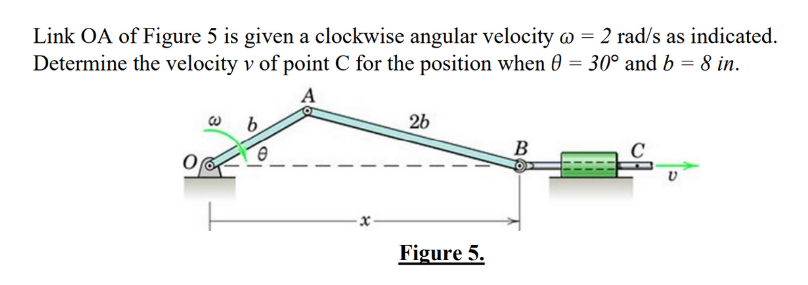

Transcribed Image Text:Link OA of Figure 5 is given a clockwise angular velocity w = 2 rad/s as indicated.
Determine the velocity v of point C for the position when 0 = 30° and b = 8 in.
b
2b
B
Figure 5.
Expert Solution
This question has been solved!
Explore an expertly crafted, step-by-step solution for a thorough understanding of key concepts.

Step by stepSolved in 2 steps with 4 images

Knowledge Booster

Similar questions
- Draw a six-bar linkage mechanism used for holding an industrial stirrer. Points A, B, and E are on a straight line on link 2. Points B, C, and G are on a straight line on link 3. The input link 2 rotates with a constant angular velocity a of 3 rad/s (cw) at the instant. O2=0 (a) Complete the acceleration polygon according to the drawing scale given, and find the angular accelerations Oy, 04, as, and as of links 3, 4, 5, and 6, and the acceleration Ap of point F. The position of link 2 is given as input. Write down the vector loop equations of the linkage for analytical position analysis and identify the unknowns in the equations. Note: Round off all your answers to two decimal places. Dimensions: AB= 40.00 mm BE = 20.00 mm BC = 33.54 mm CG= 33.54 mm CD = 18.03 mm EF = 43.00 mm FG = 29.15 mmarrow_forwardThe disc rolls such that the angular acceleration= 4 rad/s2 and and the angular velocity=2 rad/s. Assume A lies on the periphery of the disc, 150 mm from C. What is the acceleration of point B on the link and the link's angular acceleration?arrow_forwardPLEASE ANSWER ASAP. WILL RATE IF CORRECT!arrow_forward
- Link OA of Figure 5 is given a clockwise angular velocity @ = 2 rad/s as indicated. Determine the velocity v of point C for the position when 0 = 30° and b = 8 in. A b 26 Figure 5. B Varrow_forwardThe following mechanism is scaled so that the distance from O2 to B is 4cm. Theta two is 135 degreesand is rotating at 120 rpm CCWDetermine the angular velocity of link 3 and the velocity of D3 (which is on link 3) at this instant usinga) Velocity Polygonsb) Loop Closurearrow_forward(Read Image) (Answer: vC = 0.965 ft/sec right)arrow_forward
- PROBLEM STATEMENT: Draw the 3D version of the given figure below using Solidworks. At that instant shown below, Q₂F 15 inch, Q4B = 14 inch, Q4D = 6 inch, Q4E = 15 inch, Q2 Q4 15 inch. The crank Q4D is rotating uniformly counterclockwise at 150 rpm. Find the absolute instantaneous linear velocity in fps of point F and E and the absolute instantaneous angular velocity in rpm of the variable length crank Q₂F using your chosen method (1, 2 and 3) and Method 4. Variable: Ꮎ 6 0 Q2 5 B 30 F Q4 3 PE - 1arrow_forward(read image)arrow_forwardThe speed of Crank Q2A is 71.62 rpm counter-clockwise. Q2A is 2 ft long and the rest of the members are drawn to scale as shown in the figure. Solve for the velocity of point A and find the velocity of point B, C, D, E, F and G in fps using the INSTANTANEOUS AXIS OF ROTATION ONLY!. Ks = 1 inch : 1 foot Kv = 1 inch : 10 fpsarrow_forward
- Find the acceleration of points A and B also the angular accelerations of links 3 and 4 using Relative Acceleration Method. Input link has constant angular velocity. Note that the drawing is not in scale. @2=1 rad/s 02 O 2 30° A 3 B (0) 04 02A=4" AB=7" 0204=9" 04B-8"arrow_forwardäbö 25 In a mechanism as shown in figure, the crank OA is 100 mm long and rotates in a clockwise direction at a speed of 100 rpm. The link BC is 200 mm long and the link AB is 300 mm long. (a) Draw space diagram and (b) draw the velocity .diagram of point A B 300 mm 30° 100 mm Aarrow_forwardA piston, connecting rod and crank mechanism is shown in the diagram. The crank rotates at a constant velocity of 300 rad/s. Find the acceleration of the piston and the angular acceleration of the link BC. The giagram is not drawn to scale. Crank AB is rotating in clockwise direction.arrow_forward
arrow_back_ios
SEE MORE QUESTIONS
arrow_forward_ios
Recommended textbooks for you
- Elements Of ElectromagneticsMechanical EngineeringISBN:9780190698614Author:Sadiku, Matthew N. O.Publisher:Oxford University Press
 Mechanics of Materials (10th Edition)Mechanical EngineeringISBN:9780134319650Author:Russell C. HibbelerPublisher:PEARSON
 Thermodynamics: An Engineering ApproachMechanical EngineeringISBN:9781259822674Author:Yunus A. Cengel Dr., Michael A. BolesPublisher:McGraw-Hill Education
  Control Systems EngineeringMechanical EngineeringISBN:9781118170519Author:Norman S. NisePublisher:WILEY
 Mechanics of Materials (MindTap Course List)Mechanical EngineeringISBN:9781337093347Author:Barry J. Goodno, James M. GerePublisher:Cengage Learning
 Engineering Mechanics: StaticsMechanical EngineeringISBN:9781118807330Author:James L. Meriam, L. G. Kraige, J. N. BoltonPublisher:WILEY
Elements Of Electromagnetics
Mechanical Engineering
ISBN:9780190698614
Author:Sadiku, Matthew N. O.
Publisher:Oxford University Press
Mechanics of Materials (10th Edition)
Mechanical Engineering
ISBN:9780134319650
Author:Russell C. Hibbeler
Publisher:PEARSON
Thermodynamics: An Engineering Approach
Mechanical Engineering
ISBN:9781259822674
Author:Yunus A. Cengel Dr., Michael A. Boles
Publisher:McGraw-Hill Education
Control Systems Engineering
Mechanical Engineering
ISBN:9781118170519
Author:Norman S. Nise
Publisher:WILEY
Mechanics of Materials (MindTap Course List)
Mechanical Engineering
ISBN:9781337093347
Author:Barry J. Goodno, James M. Gere
Publisher:Cengage Learning
Engineering Mechanics: Statics
Mechanical Engineering
ISBN:9781118807330
Author:James L. Meriam, L. G. Kraige, J. N. Bolton
Publisher:WILEY