
Elements Of Electromagnetics
7th Edition
ISBN: 9780190698614
Author: Sadiku, Matthew N. O.
Publisher: Oxford University Press
expand_more
expand_more
format_list_bulleted
Related questions
Question
Solve this problem and show all of the work
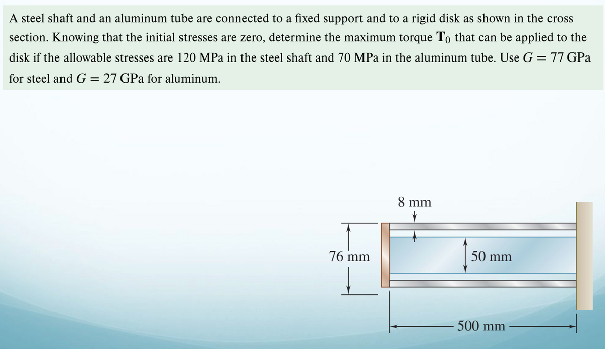

Transcribed Image Text:A steel shaft and an aluminum tube are connected to a fixed support and to a rigid disk as shown in the cross
section. Knowing that the initial stresses are zero, determine the maximum torque To that can be applied to the
disk if the allowable stresses are 120 MPa in the steel shaft and 70 MPa in the aluminum tube. Use G = 77 GPa
for steel and G = 27 GPa for aluminum.
76 mm
8 mm
50 mm
500 mm
Expert Solution
This question has been solved!
Explore an expertly crafted, step-by-step solution for a thorough understanding of key concepts.

Step by stepSolved in 2 steps with 1 images

Knowledge Booster

Similar questions
- 3. The stepped shaft shown is supported by bearings at A and B. Determine the maximum stress in the shaft due to the applied torques. The shoulder fillet at the junction of each shaft has a radius of r= 3 mm 27 N.m 54 N.m 27 N.m 30 mm A 15 mmarrow_forwardA composite shaft is made by slipping a bronze tube of 3-in. outer diameteran -in. inner diameter over a solid steel shaft of the same length and 2-in.-diameter. The two components are then fastened rigidly together at their ends. What is the largest torque that can be carried by the composite shaft if the working shear stresses are 8 ksi for bronze and 12 ksi for the steel? For bronze, G = 6 x 10⁶ psi, and for steel, G = 12 x 106 psiarrow_forward3. Two solid 1.75 in.-diameter steel shafts are connected by the gears shown. The shaft lengths are L₁= 6 ft and L2 = 10 ft. Assume that the shear modulus of both shafts is G= 12,000 ksi and that the bearings shown allow free rotation of the shafts. If the torque applied at gear D is TD= 225 lb-ft, determine (a) the internal torques T₁ and 72 in the two shafts. (b) the angles of twist 1 and 2. (c) the rotation angles 3 and þc of gears B and G. (d) the rotation angle of gear D. 4₁ (1) 30 teeth 54 teeth B (2)arrow_forward
- 2. A composite shaft is subjected to two torques as shown below. Shaft AB is a solid aluminum (G = 25 GPa) shaft and is welded to brass (G = 37 GPa) shaft BCD. Segment BC of the brass shaft is solid and the segment CD is hollow with inner diameter of 40 mm. Determine the maximum shear stresses in the aluminum and brass shafts, and the angle of twist of end A. 60 mm T = 1600 N - m 36 mm TA = S00 N - m 250 mm 375 mm 400 mmarrow_forwardThe mechanism below consists of a solid shaft with a diameter of 2 in between A and B and a hollow shaft with an outside diameter of 7 in and a thickness of 1/2 in between B and C. A torque T = 3 kip-in is applied as shown at A and two forces, each P = 322 lb, are applied as shown at the ends of the levers connected to Point B. Determine the shear stress that occurs on the exterior of the hollow shaft between B and C. Express answer in nearest whole psi.arrow_forwardThe rigid wrench (not the brand Rigid sold at Home Depot!) shown is used to loosen a stuck nut at the top of a 4 mm radius smooth shafted bolt that is fixed supported at the base A. Determine the largest force F that can be applied if the bolt has a maximum shear stress of for this maximum torque value. G=75 GPa 18 MPa. Also determine the distance each force will move Ans: 6.03 N F. 150 mm 150 mm 80 mmarrow_forward
- A steel shaft and an aluminum tube are connected to a fixed support and to a rigid disk as shown in the cross section. Knowing that the initial stresses are zero, determine the maximum torque T0 that can be applied to the disk if the allowable stresses are 120 MPa in the steel shaft and 70 MPa in the aluminum tube. Use G= 77 GPa for steel and G = 27 GPa for aluminum.arrow_forwardA steel shaft with a length of 3.00 m. One meter of the steel is contained in a brass tube and firmly attached. The diameter d1 = 70 mm and the diameter d2 = 90 mm. Brass G = 39GPa and steel G = 77.20 GPa. Determine: The torque that can be applied if the deformation at one end is 10 degrees. Answer: T = 8.64 kN – m The torque that can be applied if the maximum shear stress in brass is 70MPa and in steel is 110MPa. Answer: T = 6.352 kN – m Recommendation: analyze by segments. The first segment is only brass, then the composite part between brass and steel, and the last part only steel. In the composite segment, use only one material. In this same segment, equalize the deformations.arrow_forwardA steel shaft is to be manufactured either as a solid circular or as circular tube. The shaft is required to transmit a torque of 1200 Nm without exceeding an allowable shear stress of 40 MPa, nor an allowable rate of twist of 0.75º/m. For G = 78GPa, determine: The required diameter do of the solid shaft. The required outer diameter d2 of the hollow shaft if the thickness t of the shaft is specified as one-tenth of the outer diameter. The ratio of diameters (that is, the ratio d2/do and the ratio of the weights of the hollow and solid shafts.arrow_forward
- A 88-N·m torque is applied to a hollow shaft having the cross section shown. Neglecting the effect of stress concentrations, determine the shearing stress at points a and b. The shearing stress at point a is MPa. The shearing stress at point b is MPa.arrow_forwardThe solid rod AB has a diameter dAB5 60 mm and is made of a steel for which the allowable shearing stress is 85 MPa. The pipe CD, which has an outer diameter of 90 mm and a wall thickness of 6 mm, is made of an aluminum for which the allowable shearing stress is 54 MPa. Determine the largest torque T that can be applied at Aarrow_forwardThe halves of the coupling are held together by four 5/8-in.-diameter bolts. The working stresses are 12 ksi for shear in the bolts and 15 ksi for bearing in the coupling. Find the largest torque T that can be safely transmitted by the coupling. Assume that the forces in the bolts have equal magnitudes. 0.5 in. 3.5 in.arrow_forward
arrow_back_ios
SEE MORE QUESTIONS
arrow_forward_ios
Recommended textbooks for you
- Elements Of ElectromagneticsMechanical EngineeringISBN:9780190698614Author:Sadiku, Matthew N. O.Publisher:Oxford University Press
 Mechanics of Materials (10th Edition)Mechanical EngineeringISBN:9780134319650Author:Russell C. HibbelerPublisher:PEARSON
 Thermodynamics: An Engineering ApproachMechanical EngineeringISBN:9781259822674Author:Yunus A. Cengel Dr., Michael A. BolesPublisher:McGraw-Hill Education
  Control Systems EngineeringMechanical EngineeringISBN:9781118170519Author:Norman S. NisePublisher:WILEY
 Mechanics of Materials (MindTap Course List)Mechanical EngineeringISBN:9781337093347Author:Barry J. Goodno, James M. GerePublisher:Cengage Learning
 Engineering Mechanics: StaticsMechanical EngineeringISBN:9781118807330Author:James L. Meriam, L. G. Kraige, J. N. BoltonPublisher:WILEY
Elements Of Electromagnetics
Mechanical Engineering
ISBN:9780190698614
Author:Sadiku, Matthew N. O.
Publisher:Oxford University Press
Mechanics of Materials (10th Edition)
Mechanical Engineering
ISBN:9780134319650
Author:Russell C. Hibbeler
Publisher:PEARSON
Thermodynamics: An Engineering Approach
Mechanical Engineering
ISBN:9781259822674
Author:Yunus A. Cengel Dr., Michael A. Boles
Publisher:McGraw-Hill Education
Control Systems Engineering
Mechanical Engineering
ISBN:9781118170519
Author:Norman S. Nise
Publisher:WILEY
Mechanics of Materials (MindTap Course List)
Mechanical Engineering
ISBN:9781337093347
Author:Barry J. Goodno, James M. Gere
Publisher:Cengage Learning
Engineering Mechanics: Statics
Mechanical Engineering
ISBN:9781118807330
Author:James L. Meriam, L. G. Kraige, J. N. Bolton
Publisher:WILEY