Introductory Circuit Analysis (13th Edition)
13th Edition
ISBN: 9780133923605
Author: Robert L. Boylestad
Publisher: PEARSON
expand_more
expand_more
format_list_bulleted
Question

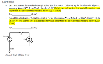
Transcribed Image Text:LED Biasing
⚫ LED max current for standard through-hole LEDs is ~20mA. Calculate R₁ for the circuit in Figure 15
assuming VLED=2.0V, ILED=20mA, Supply+=9.0V (In lab, we will use the first available resistor value
larger than the calculated resistance to ensure ILED < 20mA).
R₁=
(9.0V)
• Repeat the calculation of R₁ for the circuit in Figure 15 assuming VLED=3.0V, ILED=20mA, Supply+=9.0V
(In lab, we will use the first available resistor value larger than the calculated resistance to ensure ILED<
20mA).
R₁=
(9.0V)
Supply+
GND
R1
LED
Figure 15: Simple LED Blas Circuit
Expert Solution
This question has been solved!
Explore an expertly crafted, step-by-step solution for a thorough understanding of key concepts.
Step by stepSolved in 2 steps with 1 images

Knowledge Booster
Similar questions
- * The 4-layer diode in below figure is biased such that it is in the forward-conduction region. Detemine the anode current for and VBRF) = 20 V, VBE = 0.7 V, VCE(sat) = 0.2 V. Rs 1.0 kn VBIAS 25 Varrow_forwardDiodes in Series and Parallel Diodes in Series ⚫ For the circuit in Figure 16, calculate Vout and R₁. Given: ILED=20mA, Supply+=9.0V, VLED=2.0V. Vout= R1= • Repeat the calculation for Vout and R₁. Given: ILED=20mA, Supply+=9.0V, VLED=3.0V. Vout= R₁= Supply+ GND R1 LED LED Figure 16:LED Circuit + Vaucarrow_forwardpoints) For the circuit shown below, sketch to scale the output V, waveform and draw the transfer characteristic (V. versus Vi), Assume the diodes are ideal. V₁ =15-sin wt Zloks www loks # HIF 4V + Voarrow_forward
- For the circuit shown in the Figure, if the diodes are silicon diodes with Vp(on)=0.7 V, and VIN=50 sin wt V, V1 =6 V and V2 = 16 V, then the value of VouTP-p) is: R, D VaN Vout v1事 2章 Oa. 25.4 V Ob. 27.4 V Oc. 29.4 V Od. 23.4 Varrow_forwardDraw the changes in Vi and Id of the ideal diode half-wave rectifier circuit in the figure. The frequency of the sine signal here will be taken as 50Hz. (Changes in Vi and Id will be drawn!!!)arrow_forwardHelli. I only need the last part. Plotting power vs voltage if used as a solar cell and give the definition of fill factor. Tnxarrow_forward
- Example (2-2):- Referring to the series diode configuration of Figure (2-14) (a), and by employing the diode characteristics of Figure (2-14)(b) determine:- VDQ, IDQ and VR ID (mA) 10. IDQ= 9.25mA 8 Q- point ID Load line VR 1KO 6- 4 2 VD(V) VDQ= 0.78 v 10varrow_forwardThis multiple choice questions from electronics lab,please solve all ,it's easy for you ????arrow_forwardExcept for FinFET and GaaFET discussed in the lecture, there are many new designs of FET. Please do a detailed study on any of them. In less than 200 words, state the advantages of it over the traditionalarrow_forward
- 2.Sketch the waveforms for the load current and load voltage for the circuit show in Figure 2. Show the peak values. Use the offset diode model in your calculations. Input voltage source could be represented as a sine waveform, given as Vin=20sin(wt +30), and RL = 20 S Figure 2 www R₁ Voutarrow_forwardQ2) Explain the working of zener diode on both forward and reverse bias. From the circuit in the Figure-2, Rs=1KO, Vz=7.2V and RL=3KN. If Vs = 12V. Find out the following DC parameters: a) Is = ?, Current passing through resistor Rs b) IL = ?, Current passing through resistor RL c) Iz = ?, Current passing through Zener Diode d) VL= ?, Output Voltage (Figure-2) Rs 1k Ohm Is Iz RL VL Vs UA723_ZD2 .3k Ohm 12 Varrow_forwardFigure Q2(a) shows the characteristic curve of a Zener diode. Analyse the characteristic curve to identify the approximate minimum Zener current Izk(min) and the approximate Zener voltage, Vz at IZK. -10 -9 -8 -7 -6 -5 -2 -1 Vz (V) + 1 3 4 6 7 8 Iz (mA) Figure Q2(a) Analyse the circuit in Figure Q2(b) to identify the minimum input voltage required to keep the diode in Zener region based on the values of the minimum Zener current and the approximated Zener voltage found in Question 2(a). R 1k2 VIN Figure Q2(b)arrow_forward
arrow_back_ios
SEE MORE QUESTIONS
arrow_forward_ios
Recommended textbooks for you
 Introductory Circuit Analysis (13th Edition)Electrical EngineeringISBN:9780133923605Author:Robert L. BoylestadPublisher:PEARSON
 Delmar's Standard Textbook Of ElectricityElectrical EngineeringISBN:9781337900348Author:Stephen L. HermanPublisher:Cengage Learning
 Programmable Logic ControllersElectrical EngineeringISBN:9780073373843Author:Frank D. PetruzellaPublisher:McGraw-Hill Education
 Fundamentals of Electric CircuitsElectrical EngineeringISBN:9780078028229Author:Charles K Alexander, Matthew SadikuPublisher:McGraw-Hill Education
 Electric Circuits. (11th Edition)Electrical EngineeringISBN:9780134746968Author:James W. Nilsson, Susan RiedelPublisher:PEARSON
 Engineering ElectromagneticsElectrical EngineeringISBN:9780078028151Author:Hayt, William H. (william Hart), Jr, BUCK, John A.Publisher:Mcgraw-hill Education,

Introductory Circuit Analysis (13th Edition)
Electrical Engineering
ISBN:9780133923605
Author:Robert L. Boylestad
Publisher:PEARSON

Delmar's Standard Textbook Of Electricity
Electrical Engineering
ISBN:9781337900348
Author:Stephen L. Herman
Publisher:Cengage Learning

Programmable Logic Controllers
Electrical Engineering
ISBN:9780073373843
Author:Frank D. Petruzella
Publisher:McGraw-Hill Education

Fundamentals of Electric Circuits
Electrical Engineering
ISBN:9780078028229
Author:Charles K Alexander, Matthew Sadiku
Publisher:McGraw-Hill Education

Electric Circuits. (11th Edition)
Electrical Engineering
ISBN:9780134746968
Author:James W. Nilsson, Susan Riedel
Publisher:PEARSON

Engineering Electromagnetics
Electrical Engineering
ISBN:9780078028151
Author:Hayt, William H. (william Hart), Jr, BUCK, John A.
Publisher:Mcgraw-hill Education,