Introductory Circuit Analysis (13th Edition)
13th Edition
ISBN: 9780133923605
Author: Robert L. Boylestad
Publisher: PEARSON
expand_more
expand_more
format_list_bulleted
Question

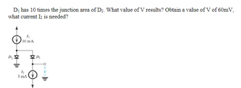
Transcribed Image Text:D₁ has 10 times the junction area of D₂. What value of V results? Obtain a value of V of 60mV,
what current I2 is needed?
D₂
10 ΠΑ
h
3 mA
Expert Solution
This question has been solved!
Explore an expertly crafted, step-by-step solution for a thorough understanding of key concepts.
Step by stepSolved in 2 steps with 1 images

Knowledge Booster
Similar questions
- In the circuit shown below, if VA= 1V and V-2V, the statuses of the diodes are (Assuming ideal diodes) D₁ VA V₂₁ D₂ ERL Vout Select one: O a D₂ is ON, D₂ is ON O b. None of these Oc. Dy is OFF, D₂ is ON O d. Dy is ON, D₂ is OFFarrow_forwardTwo silicon diodes, with a forward voltage drop of 0.7 V, are used in the circuit shown in the figure. The range of input vi for which the output voltage vo = vi, is. R ww D₁ A -1V(+ D₂ +)3Varrow_forwardPlease in typing format please ASAP for the like please clear the Please answer in typing format please ASAP for please ASAP for likearrow_forward
- You can assume any values just please note them. I just want to have this circuit working at all conditions. Or at least see the process so I can do it on my own with my own calculationsarrow_forwardFind voltage v₁ of the circuit in the Figure, where D is an ideal diode. Rs US + I R₁ VD D RL VLarrow_forwardAnalog circuit designarrow_forward
- Analyze the ON/OFF states of all diodes (D1 and D2) inthis circuit, using the ideal-diode model.arrow_forwardI have a half size breadboard,9V source, multimeter, 220 resistor, (forward biased) 1N914 diode, in series. Im reading about 9.7mA. The simulation reads close to 36mA. Can you help me to figure out if I am doing something wrong. (I lfet the battery a little unhooked so the resistor would not overheat). This image shows how I set up my circuit I need to read current first than volage the simulation has another multimeter we are to relace with a jumper wire to read voltage of the diode. We first must read circuit currrent.arrow_forwardCan you draw me a half size breadboard circuit with a 9V source, a multimeter, 220ohm resistor in series and a 1N914 forward biased diode? Im reading about 9.8mA and others are reading 35.02mA. Can you tell me what about it should read for current and voltage? The simulation has two multimeters but we only use one for the live experiment. I feel like Im getting low current reading so I may have it wired wrong.arrow_forward
- 2:50 1 LTE O Motor Warning Light Instructions PHYS&110-VHY-S21-PHYSNON-SCIMAJORSWLAB-.. STEP 3 Now add a red LED (D1 in the main schematic) in series with 500N of resistance (shown as R1 in the main schematic). How you choose to arrive at 5002 is up to you. SW1 PSB D2 D3 1N4007 5 V D1 Blue Red R3 10 ka R1 500 Q • What happens now when SW1 is (and the PSB is turned on)? • What happens if you turn the diode at D3 around? (Don't forget to turn it back the right way afterward.) • Why does this circuit use a diode at D3 instead of a pull-up resistor? (Meaning, what would happen if a resistor were used instead of the diode?) pressed ( Previous Next 14 Dashboard Calendar To Do Notifications Inboxarrow_forwarda) Design a clamper circuit so that for the input waveform V,(t) as given in Figure 4(a), the output waveform V,(t) as shown in Figure 4(b) can be produced. You shall use ideal diode as part of your circuit design and provide the analysis of your design procedure with the aid of the simplified equivalent circuits. V(t) 10v- t2 t3 t4 t5 -10V (a) V.(t) 15V t1 to t3 t4 t5 -5V (b) Figure 4arrow_forwardcan you solve this question handwritten solution step by step how did we obtain the v0 graph? my question is not a part of a graded assignmentarrow_forward
arrow_back_ios
SEE MORE QUESTIONS
arrow_forward_ios
Recommended textbooks for you
 Introductory Circuit Analysis (13th Edition)Electrical EngineeringISBN:9780133923605Author:Robert L. BoylestadPublisher:PEARSON
 Delmar's Standard Textbook Of ElectricityElectrical EngineeringISBN:9781337900348Author:Stephen L. HermanPublisher:Cengage Learning
 Programmable Logic ControllersElectrical EngineeringISBN:9780073373843Author:Frank D. PetruzellaPublisher:McGraw-Hill Education
 Fundamentals of Electric CircuitsElectrical EngineeringISBN:9780078028229Author:Charles K Alexander, Matthew SadikuPublisher:McGraw-Hill Education
 Electric Circuits. (11th Edition)Electrical EngineeringISBN:9780134746968Author:James W. Nilsson, Susan RiedelPublisher:PEARSON
 Engineering ElectromagneticsElectrical EngineeringISBN:9780078028151Author:Hayt, William H. (william Hart), Jr, BUCK, John A.Publisher:Mcgraw-hill Education,

Introductory Circuit Analysis (13th Edition)
Electrical Engineering
ISBN:9780133923605
Author:Robert L. Boylestad
Publisher:PEARSON

Delmar's Standard Textbook Of Electricity
Electrical Engineering
ISBN:9781337900348
Author:Stephen L. Herman
Publisher:Cengage Learning

Programmable Logic Controllers
Electrical Engineering
ISBN:9780073373843
Author:Frank D. Petruzella
Publisher:McGraw-Hill Education

Fundamentals of Electric Circuits
Electrical Engineering
ISBN:9780078028229
Author:Charles K Alexander, Matthew Sadiku
Publisher:McGraw-Hill Education

Electric Circuits. (11th Edition)
Electrical Engineering
ISBN:9780134746968
Author:James W. Nilsson, Susan Riedel
Publisher:PEARSON

Engineering Electromagnetics
Electrical Engineering
ISBN:9780078028151
Author:Hayt, William H. (william Hart), Jr, BUCK, John A.
Publisher:Mcgraw-hill Education,