
Introductory Circuit Analysis (13th Edition)
13th Edition
ISBN: 9780133923605
Author: Robert L. Boylestad
Publisher: PEARSON
expand_more
expand_more
format_list_bulleted
Related questions
Question
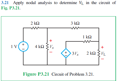

Transcribed Image Text:3.21 Apply nodal analysis to determine V₁ in the circuit of
Fig. P3.21.
1 V
+ 1
2 ΚΩ
3 ΚΩ
1 ΚΩ
4 ΚΩ ΣΕ
+
+
3Vx
2 kVL
Figure P3.21 Circuit of Problem 3.21.
Expert Solution
This question has been solved!
Explore an expertly crafted, step-by-step solution for a thorough understanding of key concepts.

Step by stepSolved in 2 steps with 1 images

Knowledge Booster

Similar questions
- R1 ŽR4 + Vsi i6 R6 R2 iz is R5 Vs2 R3 iz Q9. In the circuit, Vs1 is 121 V, Vs2 is 130 V, R1 is 3 0hm, R2 is 6 0hm, R3 is 2 Ohm, R4 is 9 Ohm, R5 is 10 Ohm, R6 is 29 Ohm. Hint: When solving the circuit using nodal analysis, ground the node where Vs1(-), Vs2(+) and R2 are connected.arrow_forwardwrite a description of the circuit function, Circuit diagram.arrow_forwardProblem F3 Design a value for R,, R, and Res such that 0.5 mA can be delivered to loads up to 18k Veco Vcc oL Rcs R1 Vcco- V+ R2 Vcc / -Vcc Q1 V- 15V /-15V R2 Lo-Vcc RLoad +arrow_forward
- RA R3 V2 D. R2 R1 For the above circuit, select ALL the extraordinary nodes that are part of a quasi-supernode. If there are none then select NONE. Note: a supernode is not a quasi-supernode. O NONE B. ODOarrow_forward2) a. For the circuit shown below, use the Branch Current Method to find an expression for i3 in terms of the circuit components. [ ans: i3 = -Va (R1 + R2)/ (RI R2 + R2 R3 +RI R3) ] b. Do at least two ranging checks on the answer of part a. c. Evaluate the voltage across R3 for the component values given. | ans: v = - 600 mV ] R, Values: Va = 1.0 v R1 = 100 2 R3 R2 = 200 2 R3 = 100 2 a. Use the Branch Current Method to derive an expression for v3 in the circuit below in terms of the other parameters of the circuit. (Hint: Solve for iz first.) W- R, ww | V,R, - V,(R, +R2)], V3= R3 R,R2 +R;R3+R,R3 [ans: b. Perform a units check on this equation. c. Perform one ranging check on this equation. wwarrow_forwardSolve the following problems on DC Circuit Equivalents or Network Theorems or Bridge Circuits.arrow_forward
- V1 + S1 L2 R2 C1 M M R4 R1 ww L1 R3 Figure 7: An RLC circuit Given the circuit in figure 7 with values R₁ = 3000, R₂ = 1000, R3 = 5000, R4 = 7000, C₁ = 1µF, L₁ = 1H, L₂ = 0.5H, V₁ = 10V. You are NOT allowed to solve the circuit with phasors, all calculations must be done in the time domain. If switch S₁ is initially closed and circuit reaches steady state and is opened at t = 0 seconds, answer the following questions. Questions (b) and (c) the switch S₁ is closed and for questions (d) to (f) the switch S₁ is opened. Redraw the circuit and clearly label all voltages and currents for each component. b) calculate the voltage over the capacitor C1 at t = 0-seconds. c) calculate the current flowing through inductor L1 at t = 0- seconds. d) calculate the natural frequency w0 and damping factor a for t > 0 seconds. e) calculate the roots (factors) of the characteristic equation. State if the circuit is underdamped, overdamped or undamped. f) calculate the current flowing through inductor L1…arrow_forwardIn the figure, if / = 8A, RỊ = 211, R2 = 8N, R3 = 100, and R4 = 120, use various tools to detemine the value of the voltage source, V. a. 133.5 V b. 1164 V c. 266.0 V d. 312.0 V e. 371.8 V f. 155.2 V R3arrow_forward1.Utilize an appropriate R-C circuit powered by a 120 V DC source. This RC circuit will be the energy source to power a single Neon Lamp. 2. Neon and other gas-based lamps often require a threshold voltage before they turn "on", i.e. emit light. The neon lamp you will use has a turn-on voltage of 70 V. In the provided LTspice model of such a neon lamp, you can explore how this light turns on and off (i.e. the current through the lamp is high when the lamp is on), when it is powered by a pulsed voltage source. Play around with the pulsed source parameters to investigate the lamp's behavior. However, keep the lamps LIspice parameters fixed (i.e. do not change the attributes of the lamp). 3. Using the RC circuit Power your Neon Lamp so that it turns on every 0.1 seconds (10 Hz frequency). The time for which it remains on is not critical, but should obviously be much less than 0.1 seconds.arrow_forward
- Just like resistors, impedance values can be combined in series or in parallel. We combine them in the same way as combining resistors, i.e., for the series connection: Zeg Z1+22+ Z3+.... For the parallel connection: Zeq = (Z+Z+Z3+...) What is the equivalent impedance of the following circuit? (Hint: you can use scientific calculator or MatLab to perform calculations involving complex numbers.) L 50 £2 300 1000 MO 400 200 102.2+19.8j O 102.2-19.8j -102.2+19.8j O-102.2 19.8jarrow_forwardPlease put all solutions neededarrow_forwardSolve it with proper soution and calculationarrow_forward
arrow_back_ios
SEE MORE QUESTIONS
arrow_forward_ios
Recommended textbooks for you
- Introductory Circuit Analysis (13th Edition)Electrical EngineeringISBN:9780133923605Author:Robert L. BoylestadPublisher:PEARSON
 Delmar's Standard Textbook Of ElectricityElectrical EngineeringISBN:9781337900348Author:Stephen L. HermanPublisher:Cengage Learning
 Programmable Logic ControllersElectrical EngineeringISBN:9780073373843Author:Frank D. PetruzellaPublisher:McGraw-Hill Education
  Fundamentals of Electric CircuitsElectrical EngineeringISBN:9780078028229Author:Charles K Alexander, Matthew SadikuPublisher:McGraw-Hill Education
 Electric Circuits. (11th Edition)Electrical EngineeringISBN:9780134746968Author:James W. Nilsson, Susan RiedelPublisher:PEARSON
 Engineering ElectromagneticsElectrical EngineeringISBN:9780078028151Author:Hayt, William H. (william Hart), Jr, BUCK, John A.Publisher:Mcgraw-hill Education,
Introductory Circuit Analysis (13th Edition)
Electrical Engineering
ISBN:9780133923605
Author:Robert L. Boylestad
Publisher:PEARSON
Delmar's Standard Textbook Of Electricity
Electrical Engineering
ISBN:9781337900348
Author:Stephen L. Herman
Publisher:Cengage Learning
Programmable Logic Controllers
Electrical Engineering
ISBN:9780073373843
Author:Frank D. Petruzella
Publisher:McGraw-Hill Education
Fundamentals of Electric Circuits
Electrical Engineering
ISBN:9780078028229
Author:Charles K Alexander, Matthew Sadiku
Publisher:McGraw-Hill Education
Electric Circuits. (11th Edition)
Electrical Engineering
ISBN:9780134746968
Author:James W. Nilsson, Susan Riedel
Publisher:PEARSON
Engineering Electromagnetics
Electrical Engineering
ISBN:9780078028151
Author:Hayt, William H. (william Hart), Jr, BUCK, John A.
Publisher:Mcgraw-hill Education,