Introductory Circuit Analysis (13th Edition)
13th Edition
ISBN: 9780133923605
Author: Robert L. Boylestad
Publisher: PEARSON
expand_more
expand_more
format_list_bulleted
Concept explainers
Question

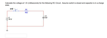
Transcribed Image Text:Calculate the voltage at 1.5¹ (milliseconds) for the following RC Circuit. Assume switch is closed and capacitor is in a charge
state.
t=0
LE
-10 V
oto
R1
1kQ
C1
1uF
Expert Solution
This question has been solved!
Explore an expertly crafted, step-by-step solution for a thorough understanding of key concepts.
Step by stepSolved in 4 steps with 3 images

Knowledge Booster
Learn more about
Need a deep-dive on the concept behind this application? Look no further. Learn more about this topic, electrical-engineering and related others by exploring similar questions and additional content below.Similar questions
- The figure displays two circuits with a charged capacitor that is to be discharged through a resistor when a switch is closed. In figure (a) below, R₁ = 23.32 and C₁ = 5.04 μF. In figure (b) below, R2 = 10.82 and C₂ = 8.10 μF. The ratio of the initial charges on the two capacitors is 902/901 = 1.61. At time t = 0, both switches are closed. At what time t do the two capacitors have the same charge? 0.0 (a) (b) Number i Unitsarrow_forwardCan you help me solve this and explain clearly I saw some answers on chegg but I don’t understand it .arrow_forwardPlz solve within 30min I vill give definitely upvote and vill give positive feedback thank youarrow_forward
- Three 20uF capacitors are connected in series with each other. A 1k ohm resistor and an LED connected in series to each other as well, but branched in parallel to all three capacitors. How long would the LED stay lit after power is removed? What current would flow through it during the charge cycle if VT=9v?arrow_forwardIf the charging resistor was twice as large as the discharging resistor in Figure 4, theamplitudes of the charging and discharging waveforms would be ________.a. The sameb. Differentarrow_forwardCalculate values of asked physical quantities of the circuit in the figure. What is the capacitance of system 23? C23 C₁ = 3.0 F What is the capacitance of system 123? C123 = F C₁ = 2.0 F What is the capacitance of system 45? C45 = F Your last answer was interpreted as follows: 1 Your last answer was interpreted as follows: 1 What is the charge in the capacitor system? C Your last answer was interpreted as follows: 1 What is the total capacitance of the system? F Value 8.8500 x 10 EO Quantity permittivity of free space capacitance capacitance capacitance capacitance capacitance Your last answer was interpreted as follows: 1 capacitance of system 23 capacitance of system 123 capacitance of system 45 Your last answer was interpreted as follows: 1 Do not leave any fields blank. If you don't know the answer, insert 1 for example. Insert the answer with 3 significant digits without rounding the answer. Constant U = 7.0 V Unit E Symbol €0 C₁ = 3.0 F C1 C₂ C3 C4 C5 C23 C₂ = 9.0 F C₂ = 3.0 F…arrow_forward
- a) With switch J2 open, close switch J1. Estimate the time it takes to do it. Obtain the equations for the voltage and current of the capacitor. Determine the energy stored by the capacitor. b) Open switch J1, close switch J2. Estimate the time it takes to do it. Obtain the equations for the voltage and current of the capacitor.arrow_forwardWhich of the following is correct for a diode ○ A diode conducts in a forward bias A diode conducts in a reverse bias ○ A diode can never conduct as it is an insulator all the time. OA diode is a bi-directional device.arrow_forward
arrow_back_ios
arrow_forward_ios
Recommended textbooks for you
 Introductory Circuit Analysis (13th Edition)Electrical EngineeringISBN:9780133923605Author:Robert L. BoylestadPublisher:PEARSON
 Delmar's Standard Textbook Of ElectricityElectrical EngineeringISBN:9781337900348Author:Stephen L. HermanPublisher:Cengage Learning
 Programmable Logic ControllersElectrical EngineeringISBN:9780073373843Author:Frank D. PetruzellaPublisher:McGraw-Hill Education
 Fundamentals of Electric CircuitsElectrical EngineeringISBN:9780078028229Author:Charles K Alexander, Matthew SadikuPublisher:McGraw-Hill Education
 Electric Circuits. (11th Edition)Electrical EngineeringISBN:9780134746968Author:James W. Nilsson, Susan RiedelPublisher:PEARSON
 Engineering ElectromagneticsElectrical EngineeringISBN:9780078028151Author:Hayt, William H. (william Hart), Jr, BUCK, John A.Publisher:Mcgraw-hill Education,

Introductory Circuit Analysis (13th Edition)
Electrical Engineering
ISBN:9780133923605
Author:Robert L. Boylestad
Publisher:PEARSON

Delmar's Standard Textbook Of Electricity
Electrical Engineering
ISBN:9781337900348
Author:Stephen L. Herman
Publisher:Cengage Learning

Programmable Logic Controllers
Electrical Engineering
ISBN:9780073373843
Author:Frank D. Petruzella
Publisher:McGraw-Hill Education

Fundamentals of Electric Circuits
Electrical Engineering
ISBN:9780078028229
Author:Charles K Alexander, Matthew Sadiku
Publisher:McGraw-Hill Education

Electric Circuits. (11th Edition)
Electrical Engineering
ISBN:9780134746968
Author:James W. Nilsson, Susan Riedel
Publisher:PEARSON

Engineering Electromagnetics
Electrical Engineering
ISBN:9780078028151
Author:Hayt, William H. (william Hart), Jr, BUCK, John A.
Publisher:Mcgraw-hill Education,