
Introductory Circuit Analysis (13th Edition)
13th Edition
ISBN: 9780133923605
Author: Robert L. Boylestad
Publisher: PEARSON
expand_more
expand_more
format_list_bulleted
Related questions
Concept explainers
Question
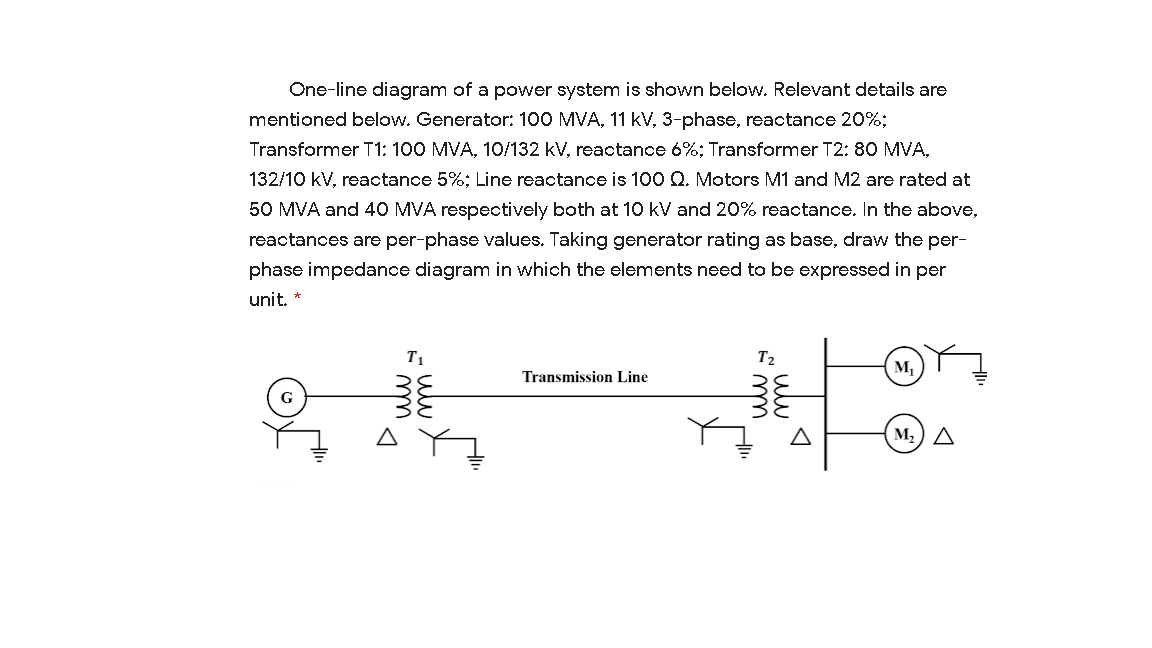

Transcribed Image Text:One-line diagram of a power system is shown below. Relevant details are
mentioned below. Generator: 100 MVA, 11 kV, 3-phase, reactance 20%;
Transformer T1: 100 MVA, 10/132 kV, reactance 6%; Transformer T2: 80 MVA,
132/10 kV, reactance 5%; Line reactance is 100 Q. Motors M1 and M2 are rated at
50 MVA and 40 MVA respectively both at 10 kV and 20% reactance. In the above,
reactances are per-phase values. Taking generator rating as base, draw the per-
phase impedance diagram in which the elements need to be expressed in per
unit. *
T1
M,
Transmission Line
G
M2) A
Expert Solution
This question has been solved!
Explore an expertly crafted, step-by-step solution for a thorough understanding of key concepts.

This is a popular solution

Trending nowThis is a popular solution!

Step by stepSolved in 6 steps with 1 images

Knowledge Booster


Learn more about
Need a deep-dive on the concept behind this application? Look no further. Learn more about this topic, electrical-engineering and related others by exploring similar questions and additional content below.Similar questions
- 2.5.3 A three phase power system has two generator connected in parallel to a transformer and subsequently to a 230 kV transmission line. The ratings for the components are given as below: Generator 1:10 MVA, reactance of 12%. Generator 2: 5 MVA, reactance of 8%. Transformer: 15 MVA, reactance of 6% Transmission line: impedance of 4+j60 2, for which the reactances in percentage are based on the ratings of the respective components. Obtain the reactance and impedance values of the components in the system in percentage, based on 15 MVA and rated voltage of the components.arrow_forward1. A single-phase power system as shown in Figure 1 consists of a 240 V, 60 Hz generator supplying a load, Zod = 8 + j6 Q through a transmission line of impedance, Zne = 0.08 + j0.14 Q. Answer the following questions: (1) transformer, T; and T2. Determine the voltage at the load and transmission line losses without the (ii) Determine the voltage at the load and transmission line losses with the transformer, T, and T2. T1 T2 1:10 10:1 IG Zaine Zioad source Figure 1arrow_forwardA 4-bus three-phase power system consists of the following equipment: • Generator 1 connected to bus 1 with a rated power of 20MVA, rated voltage of 20 kV, and a series reactance of 0.4 p.u. • Generator 2 connected to bus 5, with a rated power of 12MVA, rated voltage of 10 kV, and a series reactance of 0.3 p.u. Transformer 1 connected between buses 1 and 2, is wye-wye connected with a rated power of 20 MVA, rated voltages 20/100 kV, and a series reactance of 0.1 p.u. • Transformer 2 connected between buses 4 and 5, is wye-wye connected with a rated power of 12 MVA, rated voltages 12/110 kV, and a series reactance of 0.15 p.u. • Transmission Line 2-3 connects buses 2 and 3 and had a series impedance of 50 + j75 ohms. • Transmission Line 3-4 connects buses 3 and 4 and had a series impedance of 40 + j80 ohms. • Load A connected to bus 3 and abosorbes20 MW and 10 MVAR. The voltage at bus 3 is 105 kV. 1) Draw the one-line diagram for the system. 2) Draw the per-unit, per phase…arrow_forward
- A 12 MVA, 132/6.6 kV, transformer having a reactance of 0.15 pu is fed from an infinite bus. The transformer feeds two motor each 6 MVA, 6.6 kV. Each motors has a transient reactance of 0.14 pu and a subtransient reactance of 0.30 pu based on its own rating. A three phase balanced fault occurs at the terminals of one motor as shown in the figure below. Find the subtransient fault current and subtransient current in breaker. M1) 132/6.6 KV СВ 38 CB Infinite Bus M2 Faultarrow_forwardQUESTION ONE A three-phase 20 MVA, 11 kV generator has a reactance of 10% and is connected via a bank of three single-phase transformers to a transmission line whose series reactance is 100 2. The transmission line is supplying a load of 10 MVA at 10 kV and 0.8 power factor. The transformer bank at the generator end is connected in delta on the generator side and in star on the transmission line side and the transformer on the load side is star-star connected. Each of the single phase transformers in the bank of transformers is rated at 10 MVA, 11/110 kV with a reactance of 8%. Draw the pu circuit diagram for a system base of 10 MVA, 15 kV in the load circuit. Calculate the voltage at the generator terminals.arrow_forwardA 10 MVA three phase load is to be served by a three phase transformer at aline voltage of 13.8 kV. The supply side voltage(line-line) is 138 kV. Varioussingle phase transformers are available in the warehouse but all havewindings with voltage ratings under 100 kV and current ratings under 250 A.Is it possible to serve the load using only three single phase transformers? Ifso, specify the three phase connections and the low and high voltage ratingsof the single phase transformers.arrow_forward
arrow_back_ios
arrow_forward_ios
Recommended textbooks for you
- Introductory Circuit Analysis (13th Edition)Electrical EngineeringISBN:9780133923605Author:Robert L. BoylestadPublisher:PEARSON
 Delmar's Standard Textbook Of ElectricityElectrical EngineeringISBN:9781337900348Author:Stephen L. HermanPublisher:Cengage Learning
 Programmable Logic ControllersElectrical EngineeringISBN:9780073373843Author:Frank D. PetruzellaPublisher:McGraw-Hill Education
  Fundamentals of Electric CircuitsElectrical EngineeringISBN:9780078028229Author:Charles K Alexander, Matthew SadikuPublisher:McGraw-Hill Education
 Electric Circuits. (11th Edition)Electrical EngineeringISBN:9780134746968Author:James W. Nilsson, Susan RiedelPublisher:PEARSON
 Engineering ElectromagneticsElectrical EngineeringISBN:9780078028151Author:Hayt, William H. (william Hart), Jr, BUCK, John A.Publisher:Mcgraw-hill Education,
Introductory Circuit Analysis (13th Edition)
Electrical Engineering
ISBN:9780133923605
Author:Robert L. Boylestad
Publisher:PEARSON
Delmar's Standard Textbook Of Electricity
Electrical Engineering
ISBN:9781337900348
Author:Stephen L. Herman
Publisher:Cengage Learning
Programmable Logic Controllers
Electrical Engineering
ISBN:9780073373843
Author:Frank D. Petruzella
Publisher:McGraw-Hill Education
Fundamentals of Electric Circuits
Electrical Engineering
ISBN:9780078028229
Author:Charles K Alexander, Matthew Sadiku
Publisher:McGraw-Hill Education
Electric Circuits. (11th Edition)
Electrical Engineering
ISBN:9780134746968
Author:James W. Nilsson, Susan Riedel
Publisher:PEARSON
Engineering Electromagnetics
Electrical Engineering
ISBN:9780078028151
Author:Hayt, William H. (william Hart), Jr, BUCK, John A.
Publisher:Mcgraw-hill Education,