Structural Analysis
6th Edition
ISBN: 9781337630931
Author: KASSIMALI, Aslam.
Publisher: Cengage,
expand_more
expand_more
format_list_bulleted
Concept explainers
Question
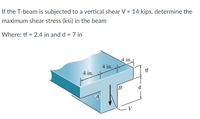
If the T-beam is subjected to a vertical shear V = 14 kips, determine the maximum shear stress (ksi) in the beam
Where: tf = 2.4 in and d = 7 in

Transcribed Image Text:If the T-beam is subjected to a vertical shear V = 14 kips, determine the
maximum shear stress (ksi) in the beam
Where: tf = 2.4 in and d = 7 in
4 in.
4 in.
tf
4 in.
d
A
Expert Solution
This question has been solved!
Explore an expertly crafted, step-by-step solution for a thorough understanding of key concepts.
Step by stepSolved in 2 steps with 3 images

Knowledge Booster
Learn more about
Need a deep-dive on the concept behind this application? Look no further. Learn more about this topic, civil-engineering and related others by exploring similar questions and additional content below.Similar questions
- Consider a point in a structural member that is subjected to plane stress. Normal and shear stress magnitudes acting on horizontal and vertical planes at the point are Sx = 17 ksi, Sy = 24 ksi, and Sxy= 16 ksi. (a) Determine the principal stresses (1 > 2) and the maximum in-plane shear stress Tmax acting at the point. (b) Find the smallest rotation angle 0, (counterclockwise is positive, clockwise is negative) that will rotate to principal directions. Then show these stresses in an appropriate sketch (e.g., see Figure 12.15 or Figure 12.16) Answers: Opl = Op2 = Tmax = Sxy 0 ksi. ksi. ksi.arrow_forwardQUESTION 3) A horizontal beam AD is supported by an inclined strut CB and carries a load of 15 kN at joint D in the figure. The strut, which consist of two bars each of thickness 40 mm, is connected to the beam by a rivet passing through the three bars meeting at joint C. The allowable shear stress and bearing stress are t-60 MPa and o=120 MPa, respectively. a) Determine the required diameter of the rivet at the hinge C that carry safely by the given system. b) If the diameter rivet used on the support A is 20 mm check whether this rivet diameter is sufficient for the given system. 0.8m Im 0.6m 15 kN В Beam AD 20mm Strut CB 40mm 100mm 40mm 50mm 100mm Detail of joint C Detail of joint Aarrow_forwardCheck the cross-section for bending if the allowable normal stress is o =±120 MPa. a: + + 1 = 4 m a = 15 cm q = 3 kN/m a +arrow_forward
- Consider a point in a structural member that is subjected to plane stress. Normal and shear stress magnitudes acting on horizontal and vertical planes at the point are Sy-17 MPa, S, - 60 MPa, and Swy- 29 MPa. (a) Draw Mohr's circle for this state of stress. (b) Determine the principal stresses (ơp > op2) and the maximum in-plane shear stress Tmax acting at the point. (c) Find the smallest rotation angle 0, (counterclockwise is positive, clockwise is negative) that will rotate to principal directions. Then show these stresses in an appropriate sketch (e.g, see Figure 12.15 or Figure 12.16) Say Answers: MPa. Opl = MPa. MPa. Tmax = 0, =arrow_forwardConsider a point in a structural member that is subjected to plane strèss. Normal and shear stress magnitudes acting on horizontal and vertical planes at the point are S= 24 MPa, Sy= 34 MPa, and Sy= 31 MPa. (a) Determine the principal stresses (o,1 > O2) and the maximum in-plane shear stress Tmax acting at the point. (b) Find the smallest rotation angle 0, (counterclockwise is positive, cločkwise is negative) that will rotate to principal directions. Then show these stresses in an appropriate sketch (e.g., see Figure 12.15 or Figure 12.16) Answers: MPа. MPa. Op2 = MPa. Imax =arrow_forwardProblem 5: The stresses on the x-y-axes are o, = 8 ksi, o, = 12 ksi, and Ty = -5 ksi. Draw the Mohr's circle for this stress state. Identify the maximum shear stress from the Mohr's circle, and draw the maximum shear stress element, specifying its orientation.arrow_forward
- Consider a point in a structural member that is subjected to plane stress. Normal and shear stress magnitudes acting on horizontal and vertical planes at the point are Sx = 37 MPa, Sy = 10 MPa, and Sxy = 41 MPa. (a) Determine the principal stresses (6,] > 6,2) and the maximum in-plane shear stress Tmax acting at the point. (b) Find the smallest rotation angle 0, (counterclockwise is positive, clockwise is negative) that will rotate to principal directions. Then show these stresses in an appropriate sketch (e.g., see Figure 12.15 or Figure 12.16) Answers: MPa. Opl = MPa. Op2 = Tmax = MPa.arrow_forwardIn figure shown, the allowable normal stress is 3.5 ksi, allowable shear stress is 1.1 ksi, If t 1.9 in. and b= 3.8 in., 3 in. a. determine the largest P, which is vertical, the frame can 3 in. carry 30 b. determine the largest P, which is normal to AC, the frame can carryarrow_forward1.1arrow_forward
arrow_back_ios
SEE MORE QUESTIONS
arrow_forward_ios
Recommended textbooks for you

 Structural Analysis (10th Edition)Civil EngineeringISBN:9780134610672Author:Russell C. HibbelerPublisher:PEARSON
 Principles of Foundation Engineering (MindTap Cou...Civil EngineeringISBN:9781337705028Author:Braja M. Das, Nagaratnam SivakuganPublisher:Cengage Learning
 Fundamentals of Structural AnalysisCivil EngineeringISBN:9780073398006Author:Kenneth M. Leet Emeritus, Chia-Ming Uang, Joel LanningPublisher:McGraw-Hill Education
 Traffic and Highway EngineeringCivil EngineeringISBN:9781305156241Author:Garber, Nicholas J.Publisher:Cengage Learning


Structural Analysis (10th Edition)
Civil Engineering
ISBN:9780134610672
Author:Russell C. Hibbeler
Publisher:PEARSON

Principles of Foundation Engineering (MindTap Cou...
Civil Engineering
ISBN:9781337705028
Author:Braja M. Das, Nagaratnam Sivakugan
Publisher:Cengage Learning

Fundamentals of Structural Analysis
Civil Engineering
ISBN:9780073398006
Author:Kenneth M. Leet Emeritus, Chia-Ming Uang, Joel Lanning
Publisher:McGraw-Hill Education


Traffic and Highway Engineering
Civil Engineering
ISBN:9781305156241
Author:Garber, Nicholas J.
Publisher:Cengage Learning