Structural Analysis
6th Edition
ISBN: 9781337630931
Author: KASSIMALI, Aslam.
Publisher: Cengage,
expand_more
expand_more
format_list_bulleted
Concept explainers
Question
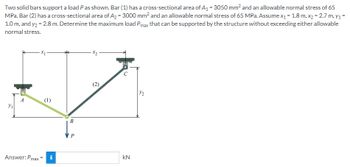
Two solid bars support a load P as shown. Bar (1) has a cross-sectional area of A, = 3050 mm? and an allowable normal stress of 65
MPa. Bar (2) has a cross-sectional area of A2 = 3000 mm? and an allowable normal stress of 65 MPa. Assume x1 = 1.8 m. x2 = 2.7 m. y1 =
1.0 m, and y2 = 2.8 m. Determine the maximum load Pmax that can be supported by the structure without exceeding either allowable
normal stress.

Transcribed Image Text:Two solid bars support a load P as shown. Bar (1) has a cross-sectional area of A₁ = 3050 mm² and an allowable normal stress of 65
MPa. Bar (2) has a cross-sectional area of A₂ = 3000 mm² and an allowable normal stress of 65 MPa. Assume x₁ = 1.8 m, x₂ = 2.7 m, y₁=
1.0 m, and y2 = 2.8 m. Determine the maximum load Pmax that can be supported by the structure without exceeding either allowable
normal stress.
Y₁
A
(1)
Answer: Pmax= i
B
P
(2)
kN
Expert Solution
This question has been solved!
Explore an expertly crafted, step-by-step solution for a thorough understanding of key concepts.
This is a popular solution
Trending nowThis is a popular solution!
Step by stepSolved in 3 steps with 3 images

Knowledge Booster
Learn more about
Need a deep-dive on the concept behind this application? Look no further. Learn more about this topic, civil-engineering and related others by exploring similar questions and additional content below.Similar questions
- A cube of material (E = 15,000 psi, v = 0.25) of side length 2" is shown in the x, y plane. Takex positive to the right and y positive up. Determine the change in length of the cube in the three coordinate directions if 4 %3D a) The normal stress in the z direction is zero (Ans: 0.0317" in x direction) b) The normal stress in the z direction is 300 psi compression (Ans: 0.0416" in x direction) 150 psi 100 psi + 200 psiarrow_forwardSolve it fast.arrow_forwardThe stresses shown act at a point in a stressed body. The stress magnitudes are S, = 80 MPa and S, = 225 MPa, acting in the directions indicated in the figure. Using the equilibrium equation approach, determine the normal and shear stresses at this point on the inclined plane shown. Assume ß = 55°. S. Answer: Sn = MPa Snt= MPaarrow_forward
- 3. The shaft in the figure below consists of 75 mm diameter bronze segment that is rigidly joint to 50 diameter steel segment. The ends of the shaft are attached to rigid supports (fixed supports). Calculate the absolute maximum shear stress developed in each segment when the torque T = 5.1 kN-m is applied (a = 2 m and b = 1.5 m). Use G = 35 GPa for %3D %3D %3D bronze, and G = 75 GPa for steel. %3D 75 mm 50 mm A Bronze Steel C T a -arrow_forwardFor the beam shown below, b = 5 in and h = 12 in. If the beam is subjected to a transverse shear for of V = 8 kip, determine the largest shearing stress in the beam. Express your answer in psi to the nearest whole psiarrow_forwardProblem 1. A material element in plane stress is subjected to stresses: Ox = -7000 psi Oy = -3000 psi = -4000 psi Txy а) Find the stresses ox,, Oy,, and Tx, y, on an element oriented at an angle 0 = 30° clockwise from the x axis and show these stresses and on a sketch of a properly oriented element. b) Find the principal stress angles, Op1, Op2, and the principal stresses, 01,02 c) Find the maximum shear stress angles, 051, es2, and the maximum shear stresses, +Tmax- d) Show the principal stresses and maximum shear stresses on a sketch of a properly oriented elementarrow_forward
- Consider a point in a structural member that is subjected to plane stress. Normal and shear stresses acting on horizontal and vertical planes at the point are shown. If o = 25 MPa in the direction shown, determine the principal stresses at the point. 28 MPa 16 MPa O 39.2 MPa and -30.2 MPa O 31.6 MPa and -35.8 MPa 54.1 MPa and -41.3 MPa 35.8 MPa and -27.4 MPa O 27.7 MPa and -39.0 MPa Save for Later eTextbook and Media Attempts: 1 of 3 used Submit Answerarrow_forwardGiven the state of plane stress shown:1. Determine the principal stresses.2. Determine the orientation of the principal planes.3. Determine the in-plane shear stress.arrow_forward(a) A steel structural member of length = 10 ft. is supported between two fixed supports so that it cannot expand. At 68°F, there is no stress in the member. (E = 30 x 106 psi and α = 6.5 x 10⁻⁶/°F) Calculate the stress (psi) in the member at 95°F. Stress (psi) = (b) If the same structural member is not supported between two fixed supports, calculate the total elongation of the member (in.) for the same temperature change. elongation (in.) =arrow_forward
arrow_back_ios
arrow_forward_ios
Recommended textbooks for you

 Structural Analysis (10th Edition)Civil EngineeringISBN:9780134610672Author:Russell C. HibbelerPublisher:PEARSON
 Principles of Foundation Engineering (MindTap Cou...Civil EngineeringISBN:9781337705028Author:Braja M. Das, Nagaratnam SivakuganPublisher:Cengage Learning
 Fundamentals of Structural AnalysisCivil EngineeringISBN:9780073398006Author:Kenneth M. Leet Emeritus, Chia-Ming Uang, Joel LanningPublisher:McGraw-Hill Education
 Traffic and Highway EngineeringCivil EngineeringISBN:9781305156241Author:Garber, Nicholas J.Publisher:Cengage Learning


Structural Analysis (10th Edition)
Civil Engineering
ISBN:9780134610672
Author:Russell C. Hibbeler
Publisher:PEARSON

Principles of Foundation Engineering (MindTap Cou...
Civil Engineering
ISBN:9781337705028
Author:Braja M. Das, Nagaratnam Sivakugan
Publisher:Cengage Learning

Fundamentals of Structural Analysis
Civil Engineering
ISBN:9780073398006
Author:Kenneth M. Leet Emeritus, Chia-Ming Uang, Joel Lanning
Publisher:McGraw-Hill Education


Traffic and Highway Engineering
Civil Engineering
ISBN:9781305156241
Author:Garber, Nicholas J.
Publisher:Cengage Learning