
Elements Of Electromagnetics
7th Edition
ISBN: 9780190698614
Author: Sadiku, Matthew N. O.
Publisher: Oxford University Press
expand_more
expand_more
format_list_bulleted
Related questions
Concept explainers
Question
Can someone help me to solve the following question showing all work by hand and drawing in autoCAD. Thank you!

Transcribed Image Text:### Problem Description
**Objective:**
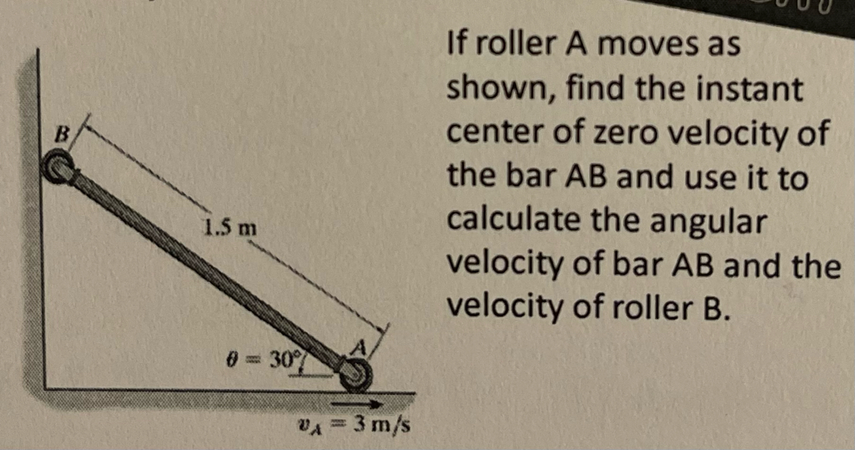
To find the instant center of zero velocity of bar AB and use it to calculate the angular velocity of bar AB and the velocity of roller B.
**Given:**
- Bar AB is shown in the diagram.
- Length of bar AB = 1.5 meters.
- Roller A moves with a velocity \( v_A = 3 \, \text{m/s} \).
- Angle \( \theta = 30^\circ \) between bar AB and the horizontal.
### Diagram Explanation
The diagram illustrates a bar AB connected to a roller A that moves horizontally. The bar makes a 30-degree angle with respect to the horizontal ground. Point B is in contact with a vertical surface.
1. **Bar AB**: A solid line indicating a rigid bar.
2. **Roller A**: A circle at the end of the bar indicating roller A, which moves horizontally to the right.
3. **Velocity \( v_A \)**: A vector shown at point A indicating a magnitude of 3 m/s directed horizontally.
4. **Angle \( \theta \)**: The bar forms a 30-degree angle with the horizontal.
### Task
- **Find the Instant Center**: Determine the point on the bar AB where its velocity is zero.
- **Calculate Angular Velocity**: Use the instant center to determine the angular motion of bar AB.
- **Determine Velocity of Roller B**: Use the angular velocity to find the velocity at point B, located at the top of the bar.
This exercise involves concepts from rigid body dynamics, focusing on relative motion and instant centers of rotation.
Expert Solution
This question has been solved!
Explore an expertly crafted, step-by-step solution for a thorough understanding of key concepts.

Step by stepSolved in 4 steps with 4 images

Knowledge Booster


Learn more about
Need a deep-dive on the concept behind this application? Look no further. Learn more about this topic, mechanical-engineering and related others by exploring similar questions and additional content below.Similar questions
- An engineer is creating a solid model of a simple gear using SolidWorks. Choose the correct statement below. The only way to generate multiple gear teeth is to sketch each tooth individually and then extrude each tooth individually. The engineer can use the linear pattern tool to create an array of gear teeth in a circular pattern about the center of the gear from a sketch of a single tooth. The engineer can use the circular pattern tool to create an array of gear teeth in a circular pattern about the center of the gear from a sketch of a single tooth. It is not possible to model gear teeth in SOLIDWORKS due to the complex shape.arrow_forwardI just need help with part D, thanksarrow_forwardPlease I want a detailed explanation of the energy method rule placed in the first line and how these numbers appeared to us. I want a detailed explanation please urgent .arrow_forward
- Use the image below to do the following i. draw 3 positions on a piece of paper. ii. Chose a Point of reference (that is not moving) set it as the center of your axis x, y and chose 3 positions and compare the positions of each Point of Interest using Calculation Your drawing iii. Share idea on how to find the linear velocity of your Points of interest using your drawing.arrow_forward3 Select the correct statement below regarding the two solid model parts shown. (A) (B) It is easiest to first draw part (B) and then use SOLIDWORKS features to create part (A). It is easiest to first draw part (A) and then use SOLIDWORKS features to create part (B). Part (B) edges were created using the fillet tool rather than the chamfer tool. Part (A) cannot be created using the extrude tool.arrow_forwardneed help getting starting drawing this in NX? What planearrow_forward
- Generate isometric drawing from multiviews using drawing tools or free - hand. Use approximate proportionate dimensions . Use plane sheet to draw or sketch isometric drawingarrow_forwardShow complete and detailed solutions. Write legibly. View Image.arrow_forwardTopic/s: Force System of a Force, Moment of a Force, Moment of a Force-Scalar Formulation,Moment of a Force-Vector Formulation, and Principle of Moment. Reminder: Kindly show the complete step-by-step solution. Please make sure that your handwriting is understandable and the picture of the solution is clear. I will rate you with “like/upvote” after. Thank you.arrow_forward
- I will rate you with “LIKE/UPVOTE," if it is COMPLETE STEP-BY-STEP SOLUTION. If it is INCOMPLETE SOLUTION and there are SHORTCUTS OF SOLUTION, I will rate you with “DISLIKE/DOWNVOTE.” THANK YOU FOR YOUR HELP. PS: If you have answered this already, DON'T ANSWER IT AGAIN; give chance to OTHER EXPERTS to answer it. I want to verify if all of you will arrive in the same final answer; thats why I ask it multiple times. If you answer it again, i'll DISLIKE all your entries/answers.arrow_forward7- Either the following text: Standardization is an activity that consists of developing rules resulting of an agreement between Manufacturers and Users". Copy it below using the stick script, straight, and of nominal height h = 7mm. 8- What is the role of the orientation marker and how is it placed on a format? 9- How is the inscription cartridge placed on a format?arrow_forwardHelp me solve this ENGR GRAPHICS question Use 0.25 Cartesian paper or 0.25 Isometric paperarrow_forward
arrow_back_ios
SEE MORE QUESTIONS
arrow_forward_ios
Recommended textbooks for you
- Elements Of ElectromagneticsMechanical EngineeringISBN:9780190698614Author:Sadiku, Matthew N. O.Publisher:Oxford University Press
 Mechanics of Materials (10th Edition)Mechanical EngineeringISBN:9780134319650Author:Russell C. HibbelerPublisher:PEARSON
 Thermodynamics: An Engineering ApproachMechanical EngineeringISBN:9781259822674Author:Yunus A. Cengel Dr., Michael A. BolesPublisher:McGraw-Hill Education
  Control Systems EngineeringMechanical EngineeringISBN:9781118170519Author:Norman S. NisePublisher:WILEY
 Mechanics of Materials (MindTap Course List)Mechanical EngineeringISBN:9781337093347Author:Barry J. Goodno, James M. GerePublisher:Cengage Learning
 Engineering Mechanics: StaticsMechanical EngineeringISBN:9781118807330Author:James L. Meriam, L. G. Kraige, J. N. BoltonPublisher:WILEY
Elements Of Electromagnetics
Mechanical Engineering
ISBN:9780190698614
Author:Sadiku, Matthew N. O.
Publisher:Oxford University Press
Mechanics of Materials (10th Edition)
Mechanical Engineering
ISBN:9780134319650
Author:Russell C. Hibbeler
Publisher:PEARSON
Thermodynamics: An Engineering Approach
Mechanical Engineering
ISBN:9781259822674
Author:Yunus A. Cengel Dr., Michael A. Boles
Publisher:McGraw-Hill Education
Control Systems Engineering
Mechanical Engineering
ISBN:9781118170519
Author:Norman S. Nise
Publisher:WILEY
Mechanics of Materials (MindTap Course List)
Mechanical Engineering
ISBN:9781337093347
Author:Barry J. Goodno, James M. Gere
Publisher:Cengage Learning
Engineering Mechanics: Statics
Mechanical Engineering
ISBN:9781118807330
Author:James L. Meriam, L. G. Kraige, J. N. Bolton
Publisher:WILEY