
Introductory Circuit Analysis (13th Edition)
13th Edition
ISBN: 9780133923605
Author: Robert L. Boylestad
Publisher: PEARSON
expand_more
expand_more
format_list_bulleted
Related questions
Question
The load impedance in the figure absorbs 2.5 kW and generates 5 kVAR The sinusoidal voltage source develops 7.5 kW. Suppose that R= 16.5Ω
A)Find the min and max of the two inductive line reactances that will satisfy these constraints.
B)For Xminobtained in part A,find the magnitudes of the total reactive power generated and the total reactive power absorbed in the circuit.
C)For Xmax obtained in part A,find the magnitudes of the total reactive power generated and the total reactive power absorbed.
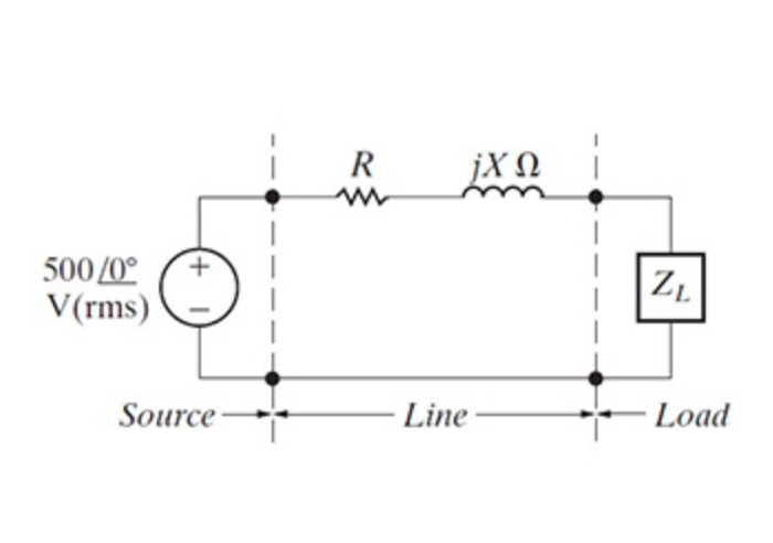

Transcribed Image Text:R
jX N
500 /0°
V(rms)
ZL
Source -
Line
Load
Expert Solution
This question has been solved!
Explore an expertly crafted, step-by-step solution for a thorough understanding of key concepts.

This is a popular solution

Trending nowThis is a popular solution!

Step by stepSolved in 4 steps

Knowledge Booster


Learn more about
Need a deep-dive on the concept behind this application? Look no further. Learn more about this topic, electrical-engineering and related others by exploring similar questions and additional content below.Similar questions
- QUESTION 3 An inductor, a capacitor, and a resistor are connected in parallel with a function generator. The inductor draws 100mA RMS, the capacitor draws 150mA RMS, and the resistor draws 200mA RMS. Find the magnitude of the total current. O 450mA RMS O 544mA RMS O 352mA RMS O 206mA RMSarrow_forwardplz solve this part step by steparrow_forwardPlease show you detailed solution Number 10 A voltage of 250 volts at 50 Hz is impressed on a circuit having a 60-ohm resistor, 35-?F capacitor, and a 0.25-henry inductor in series. Determine power factor. A. 0.979 C. 0.924 B. 0.862 D. 0.707arrow_forward
- Oscope CH1 Connection point Function Generator "LOAD" RG R2 R3 1.0027k ohms 66.98 ohms 220.6 ohms 10 Vpk 1kHz 0° L13 103.06 mH 1.015 C2 109.58 nF nF R1 99.712 ohms Oscope CH2 Connection point What is the calculated phase angle between the load voltage and current? Using the calculated phase angle and the RMS voltage/current from the meter to calculate (a) PF, (b) apparent power, (c) average power, (d) reactive power, and (e) complex power Does the amplitude of the output waveform agree with what it should be from the circuit values? Below are the measured voltages and currents.arrow_forwardParts a and d.arrow_forwardConsider the switching waveforms shown below, operating with a duty-cycle of 30%. Which statements correctly describe the switching circuit, load and circuit operation? (Multiple answers possible, but wrong answers will deduct marks) Voltage across load Voltage (V) 000 120 0000 100 80 60 40 20 30 Time (us) The load must be predominantly resistive. The average current in the load is 1.0A. The RMS current in the load is approximately 1.414A. The load must be predominantly inductive. The resistive part of the load is 200ohms. The average current in the load is 0.6A. O The resistive part of the load is 50ohms. 0 0 10 20 40 50 60 Current (A) 2 5 0.5 0 0 10 Current through load 20 W 30 Time (us) 40 50 60arrow_forward
- What does s/c and 115 ohms mean?arrow_forwardWhat's 21 22 23arrow_forwardQUESTION 11 An inductor is connected in parallel with a 6540 resistor and a function generator. The applied voltage is 42V RMS and the total current is 67mA RMS. Find the magnitude of the current through the inductor. Enter your answer in the space provided. Round your answer to one decimal place. Your answer should be in mA but do not enter the unit.arrow_forward
- An alternating current varying sinusoidally with a frequency of 50 Hz has anrms value of 20 A.a) Determine the instantaneous value at 0.0025 seconds.b) Determine the instantaneous value, 0.0125 seconds after passingthrough a positive maximum value.c) At what time, measured from a positive maximum value, will theinstantaneous current be 14.14 A?arrow_forward%VAI ۲,۷ K/s 9:- Zain 4.5G+ A step down de chopper is connected to an R-52 and L. 10 mH. The de supply voltage is 100 V. The chopper is switching at a frequency of 1 kHz with a duty cycle of 50%. Determine the load current, Jo and the peak to peak ripple current as an absolute value and as percentage of de value. ☐ О Δarrow_forwardQUESTION 10 Determine the magnitude of the current through the capacitor in the circuit below. VT = 97V RMS, ZT = 102 , R1 = 90, Xc = 60 Enter your answer in amps but do not enter the unit. Round your answer to one decimal place. L1 R1 C1 R2arrow_forward
arrow_back_ios
SEE MORE QUESTIONS
arrow_forward_ios
Recommended textbooks for you
- Introductory Circuit Analysis (13th Edition)Electrical EngineeringISBN:9780133923605Author:Robert L. BoylestadPublisher:PEARSON
 Delmar's Standard Textbook Of ElectricityElectrical EngineeringISBN:9781337900348Author:Stephen L. HermanPublisher:Cengage Learning
 Programmable Logic ControllersElectrical EngineeringISBN:9780073373843Author:Frank D. PetruzellaPublisher:McGraw-Hill Education
  Fundamentals of Electric CircuitsElectrical EngineeringISBN:9780078028229Author:Charles K Alexander, Matthew SadikuPublisher:McGraw-Hill Education
 Electric Circuits. (11th Edition)Electrical EngineeringISBN:9780134746968Author:James W. Nilsson, Susan RiedelPublisher:PEARSON
 Engineering ElectromagneticsElectrical EngineeringISBN:9780078028151Author:Hayt, William H. (william Hart), Jr, BUCK, John A.Publisher:Mcgraw-hill Education,
Introductory Circuit Analysis (13th Edition)
Electrical Engineering
ISBN:9780133923605
Author:Robert L. Boylestad
Publisher:PEARSON
Delmar's Standard Textbook Of Electricity
Electrical Engineering
ISBN:9781337900348
Author:Stephen L. Herman
Publisher:Cengage Learning
Programmable Logic Controllers
Electrical Engineering
ISBN:9780073373843
Author:Frank D. Petruzella
Publisher:McGraw-Hill Education
Fundamentals of Electric Circuits
Electrical Engineering
ISBN:9780078028229
Author:Charles K Alexander, Matthew Sadiku
Publisher:McGraw-Hill Education
Electric Circuits. (11th Edition)
Electrical Engineering
ISBN:9780134746968
Author:James W. Nilsson, Susan Riedel
Publisher:PEARSON
Engineering Electromagnetics
Electrical Engineering
ISBN:9780078028151
Author:Hayt, William H. (william Hart), Jr, BUCK, John A.
Publisher:Mcgraw-hill Education,