Elements Of Electromagnetics
7th Edition
ISBN: 9780190698614
Author: Sadiku, Matthew N. O.
Publisher: Oxford University Press
expand_more
expand_more
format_list_bulleted
Concept explainers
Question
Plz hand written otherwise skip.... If hand written i'll upvote plz fast plzzzzzz fast plzzzz

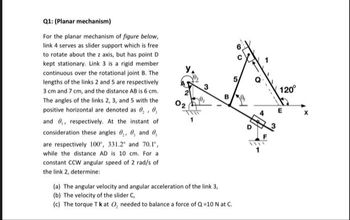
Transcribed Image Text:Q1: (Planar mechanism)
For the planar mechanism of figure below,
link 4 serves as slider support which is free
to rotate about the z axis, but has point D
kept stationary. Link 3 is a rigid member
continuous over the rotational joint B. The
lengths of the links 2 and 5 are respectively
3 cm and 7 cm, and the distance AB is 6 cm.
The angles of the links 2, 3, and 5 with the
positive horizontal are denoted as 0, 0,
and ,, respectively. At the instant of
consideration these angles 0, 0, and 0,
are respectively 100°, 331.2° and 70.1",
while the distance AD is 10 cm. For a
constant CCW angular speed of 2 rad/s of
the link 2, determine:
Y₁
3
B
(a) The angular velocity and angular acceleration of the link 3,
(b) The velocity of the slider C,
(c) The torque Tk at O₂ needed to balance a force of Q=10 N at C.
th
120°
Expert Solution
This question has been solved!
Explore an expertly crafted, step-by-step solution for a thorough understanding of key concepts.
Step by stepSolved in 2 steps with 1 images

Knowledge Booster
Learn more about
Need a deep-dive on the concept behind this application? Look no further. Learn more about this topic, mechanical-engineering and related others by exploring similar questions and additional content below.Similar questions
- Gentlemen, please help to solve a,b,c as I faced confusing questions about screw jack. Conditions are: screw jack is lifting 3.2 tonnes, screw pitch is 12 mm, diameter of the screw is 5 mm. Coefficient of friction was not given but I think we will need it for total force calculation, lets take it 0.2. a) Calculate horizontal component to move the load - what is ment here by horizontal component? b) Calculate vertical component to move the load - what is ment here by vertical component? c) Total force needed to move the load with a lever of 0.82m d) Velocity ratio (VR=distance by effort/distance by load) Distance by effort (lever)=2 x 3.14 x 0.82 = 5.15m Distance by load = pitch= 12mm= 0.012 m VR=5.15/0.012= approx 429. e) Calculate efficiency. For this we need to have MA (mechanical advantage). It can be calculated when we know total force. Efficiency=Load (3200 x 9.8) / effortarrow_forwardP) Draw the kinematic diagram of the excavator arm and calculate the mobility of the mechanismarrow_forwardplease answer, thank youarrow_forward
- Industrial Maintenance What are the speed and direction of gear D3 in Figure 6-41? see picturearrow_forwardFor the First name and Surame please use the N - Z option First name w(ab) and a(AB) are counter-clockwise Surname: r(AB) = 500mm and angle = 30 Degreesarrow_forwardSolve First one Onlyarrow_forward
- im sorry for the inconvinience , 500 d/d means 500 rpm. Its translated from turkish textbook , i forgot to translate the rpm value. Could you correct the substitutions please ?arrow_forwardb) You are given a set of six links. The lengths of the links are as follows: 6.3cm, 9.1cm,12.4cm,15.6cm,20cm,40.2cmSketch a crank-rocker mechanism you can realize using a selection of four links from the set.arrow_forwardDon't copy. I will vote accordingly marrow_forward
arrow_back_ios
arrow_forward_ios
Recommended textbooks for you
 Elements Of ElectromagneticsMechanical EngineeringISBN:9780190698614Author:Sadiku, Matthew N. O.Publisher:Oxford University Press
 Mechanics of Materials (10th Edition)Mechanical EngineeringISBN:9780134319650Author:Russell C. HibbelerPublisher:PEARSON
 Thermodynamics: An Engineering ApproachMechanical EngineeringISBN:9781259822674Author:Yunus A. Cengel Dr., Michael A. BolesPublisher:McGraw-Hill Education
 Control Systems EngineeringMechanical EngineeringISBN:9781118170519Author:Norman S. NisePublisher:WILEY
 Mechanics of Materials (MindTap Course List)Mechanical EngineeringISBN:9781337093347Author:Barry J. Goodno, James M. GerePublisher:Cengage Learning
 Engineering Mechanics: StaticsMechanical EngineeringISBN:9781118807330Author:James L. Meriam, L. G. Kraige, J. N. BoltonPublisher:WILEY

Elements Of Electromagnetics
Mechanical Engineering
ISBN:9780190698614
Author:Sadiku, Matthew N. O.
Publisher:Oxford University Press

Mechanics of Materials (10th Edition)
Mechanical Engineering
ISBN:9780134319650
Author:Russell C. Hibbeler
Publisher:PEARSON

Thermodynamics: An Engineering Approach
Mechanical Engineering
ISBN:9781259822674
Author:Yunus A. Cengel Dr., Michael A. Boles
Publisher:McGraw-Hill Education

Control Systems Engineering
Mechanical Engineering
ISBN:9781118170519
Author:Norman S. Nise
Publisher:WILEY

Mechanics of Materials (MindTap Course List)
Mechanical Engineering
ISBN:9781337093347
Author:Barry J. Goodno, James M. Gere
Publisher:Cengage Learning

Engineering Mechanics: Statics
Mechanical Engineering
ISBN:9781118807330
Author:James L. Meriam, L. G. Kraige, J. N. Bolton
Publisher:WILEY