
Introductory Circuit Analysis (13th Edition)
13th Edition
ISBN: 9780133923605
Author: Robert L. Boylestad
Publisher: PEARSON
expand_more
expand_more
format_list_bulleted
Related questions
Question
not use ai please
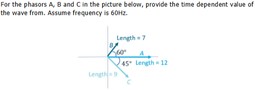

Transcribed Image Text:For the phasors A, B and C in the picture below, provide the time dependent value of
the wave from. Assume frequency is 60Hz.
Length=9
Length = 7
60°
A
45° Length 12
Expert Solution
This question has been solved!
Explore an expertly crafted, step-by-step solution for a thorough understanding of key concepts.

Step by stepSolved in 2 steps with 1 images

Knowledge Booster

Similar questions
- What is the form factor of this waveform...arrow_forwardUsing a line phasor (circle), draw the two given phasors. Use the sine function as the base function.arrow_forwardC. Draw a general sine wave V vs t and I vs t plot for a purely resistive and a purely inductive circuit and show leading lagging parameters and clearly mark the phase difference.arrow_forward
- A pure sinusoidal waveform with a period time or 0.02, has a frequency of 50Hz, define the angular frequency of the phasor representing the waveform with a simple phasor diagram.arrow_forwardA voltage wave of 250 kHz has a Vmax-5 V and Vmin=-35 V. The duty cycle of this wave is 0.875. This voltage waveform has been applied across a 2.5 µH inductor for a very long time so that steady state has been achieved. Diagrams of the wave parameters and circuit are shown in this figure: L What is the average voltage of this wave? Average voltage = 35 V Voltage (arb, unit) 1.25 Minimum current: -3.5€ Amps 1 0.75 0.5 0.25 0 4.25 05 Have you integrated the wave over full cycle? 4.75 4 -1.25 Vmax 0.5 Vmin What is the average current flowing through the inductor? Average current = 3.56 A 15 Period/s On average, there is no power consumed by the inductor. Have you considered this? What are the maximum and minimum currents that flow through the inductor? Maximum current: 0.50 Amps D= 25 TH TH Have you used the relationship for current and voltage in an inductor? Have you considered the slope of the current wave?arrow_forwardWhat is the period of the sinusoidal waveform having 100 MHz frequency.arrow_forward
- Shown in the figure below is an "RC" circuit drive by an AC power source. The AC power source has an RMS voltage of Vps (RMS) = 11.58 Volts and is running at a frequency of f = 1.326e+04 Hz. resistor has a resistance of R = 3750 2 and the capacitor has an capacitance of C = 3.17e-09 Farads. Vps R ww Write the FORMULA for the total impedance of the circuit Ztot = Write the FORMULA for the phase of the total impedance of the circuit tot = Determine the numerical value of Ztot = Determine the numerical value of Pztot= Determine the current through the circuit: • I(PEAK) = • I(RMS) = Determine the voltage across the resistor: Amps Amps S2 C degreesarrow_forwardThe pictuere shows double-beam c.r.o. waveform traces. Find the ff:• Amplitude of P• Peak-to-peak value of Q• Periodic time of both waveforms• Frequency of both waveforms• R.m.s. value of P• R.m.s. value of Q• Phase displacement of waveform Q relativeto waveform Parrow_forward3. determine the period, frequency, average value, and rms value. ||||||||||| Vertical sensitivity = 20 mV/div. Horizontal sensitivity = 10 μs/div.arrow_forward
- Shown in the figure below is an "RL" circuit drive by an AC power source. The AC power source has an RMS voltage of Vps (RMS) = 9.84 Volts and is running at a frequency of f = 8.585e+04 Hz. The resistor has a resistance of R = 2170 and the inductor has an inductance of L = 3.54e-03 Henries. Vps R ww Write the FORMULA for the total impedance of the circuit Ztot = Determine the numerical value of Ztot = 2890.5 Determine the numerical value of $z= = 41 Determine the current through the circuit: • I(PEAK) = 4.81E-3 • I(RMS) = 3.404E-3 Determine the voltage across the resistor: • VR(PEAK) = 7.387 • VR(RMS) = 5.22 ✔✔ Amps ✔Amps Write the FORMULA for the phase of the total impedance of the circuit z... = | tan-1 2701 R x Volts X Volts Determine the voltage across the inductor: • VL(PEAK) = 9.184 • VL(RMS) = 6.49 ✔ Volts Volts L R²+ WL- ✔ degrees 2 If a second circuit were connected in parallel with the inductor, this circuit would be considered as: O a low-pass filter O a capacitive switcher…arrow_forwardA Red, Voltage 2V A Blue, Current 2mA 10 time Determine the period of the waveforms Determine the frequency of the waveform For the voltage waveform, determine its phase For the current waveform, determine its phase Write an equation for both the current and voltage waveforms, including their magnitude and phasearrow_forwardA full wave rectified wave is clipped at 70.7 percent of its maximum value as shown below. find its average and rms valuearrow_forward
arrow_back_ios
SEE MORE QUESTIONS
arrow_forward_ios
Recommended textbooks for you
- Introductory Circuit Analysis (13th Edition)Electrical EngineeringISBN:9780133923605Author:Robert L. BoylestadPublisher:PEARSON
 Delmar's Standard Textbook Of ElectricityElectrical EngineeringISBN:9781337900348Author:Stephen L. HermanPublisher:Cengage Learning
 Programmable Logic ControllersElectrical EngineeringISBN:9780073373843Author:Frank D. PetruzellaPublisher:McGraw-Hill Education
  Fundamentals of Electric CircuitsElectrical EngineeringISBN:9780078028229Author:Charles K Alexander, Matthew SadikuPublisher:McGraw-Hill Education
 Electric Circuits. (11th Edition)Electrical EngineeringISBN:9780134746968Author:James W. Nilsson, Susan RiedelPublisher:PEARSON
 Engineering ElectromagneticsElectrical EngineeringISBN:9780078028151Author:Hayt, William H. (william Hart), Jr, BUCK, John A.Publisher:Mcgraw-hill Education,
Introductory Circuit Analysis (13th Edition)
Electrical Engineering
ISBN:9780133923605
Author:Robert L. Boylestad
Publisher:PEARSON
Delmar's Standard Textbook Of Electricity
Electrical Engineering
ISBN:9781337900348
Author:Stephen L. Herman
Publisher:Cengage Learning
Programmable Logic Controllers
Electrical Engineering
ISBN:9780073373843
Author:Frank D. Petruzella
Publisher:McGraw-Hill Education
Fundamentals of Electric Circuits
Electrical Engineering
ISBN:9780078028229
Author:Charles K Alexander, Matthew Sadiku
Publisher:McGraw-Hill Education
Electric Circuits. (11th Edition)
Electrical Engineering
ISBN:9780134746968
Author:James W. Nilsson, Susan Riedel
Publisher:PEARSON
Engineering Electromagnetics
Electrical Engineering
ISBN:9780078028151
Author:Hayt, William H. (william Hart), Jr, BUCK, John A.
Publisher:Mcgraw-hill Education,