
Delmar's Standard Textbook Of Electricity
7th Edition
ISBN: 9781337900348
Author: Stephen L. Herman
Publisher: Cengage Learning
expand_more
expand_more
format_list_bulleted
Related questions
Question
SOLVE ON PAPER DO NOT USE CHATGPT OR AI
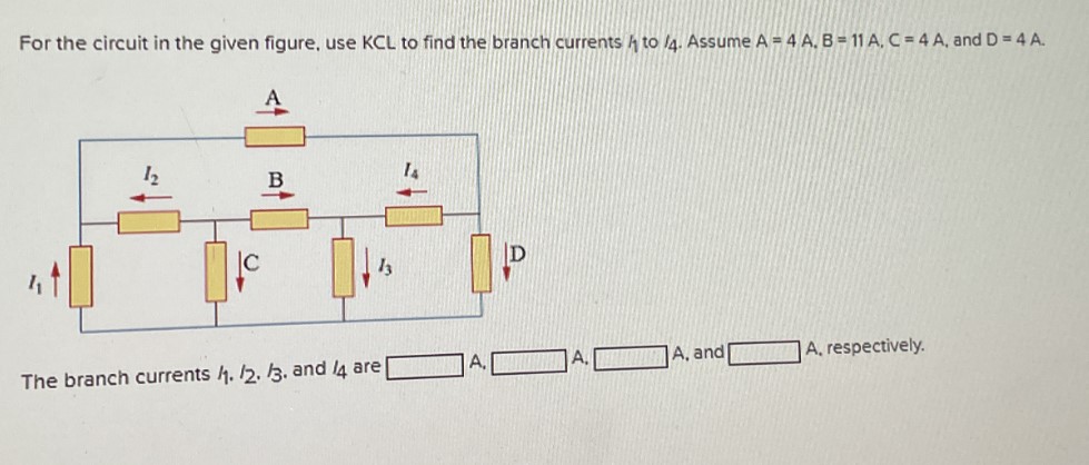

Transcribed Image Text:For the circuit in the given figure, use KCL to find the branch currents to 14. Assume A 4 A. B-11 A. C = 4 A, and D = 4 A.
12
B
|C
The branch currents 1. 12. 13. and 14 are [
A, and
A, respectively.
SAVE
AI-Generated Solution
info
AI-generated content may present inaccurate or offensive content that does not represent bartleby’s views.
Unlock instant AI solutions
Tap the button
to generate a solution
to generate a solution
Click the button to generate
a solution
a solution
Knowledge Booster

Similar questions
- B.. What is the load current for the circuit shown in the figure? Please choose one: a. 6.0 mA b. 3.0 mA C. 9.0 mA D. 7.5 mAarrow_forward*Use 4 decimal places. **Note D1 is Germanium, D2 is Silicon, For the circuit below, determine the diode voltages VD1 and VD2, diode currents ID1 and ID2, and voltage across the resistor, VRLIMIT. Use practical model. Assume r'a=150. VBIAS = 15V and RLIMIT = 1.5kohms. VD1 = Blank 1 V; VD2 = Blank 2 V; Ip1 = Blank 3 mA; Ip2 = Blank 4 mA ; VRLIMIT = Blank 5 V Capture3(1).JPG +Vo1- +VRLIMIT +VD2- Io2 VBIASarrow_forwardQuestion 3: Breadboard connections of a circuit are given in the figure below. 1- 2- GND .... ...... ...... 0.1µF 10mH 10mH 1kn a) Draw the schematic diagram of the circuit. b) Since we can observe the input signal with Channel 1 and the output signal with Channel 2, what does this circuit do? Write the type and purpose of the circuit. c) Plot the frequency versus transfer function by calculating the required frequencies. Channel 1+ Function generator Channel 2+arrow_forward
- LED flashlights use "white" LEDs which have a diode voltage drop of 4.0V. A LED flashlight has the circuit illustrated and will run off several AAA batteries that have a 1.5 VDC rating. a. What is the minimum number of AAA cells needed to turn on the flashlight. b. Would you arrange the batteries in parallel or in series? Vdd R + LED V fritzingarrow_forwardNow let's try using a pack of AA batteries (1.2 V output voltage and 0.2 Ohm internal resistance each) to replace the lead-acid battery. In order to match the car lead-acid battery, first, 10 such AA batteries need to be connected in series to form a 12V cell, while 50 such cells need to be connected in parallel (as shown in picture above; the total of 500 AA batteries are used). Find the power that is supplied to the same "car starter" using this pack of AA batteries. (Hint: for the second question, you need to find the total voltage and the internal resistance of the whole pack; you also need to find the resistance of the "car starter"; this can be done using the data of the first part of this problem)arrow_forwarduse the constant voltage drop model in analyzing the diode circuit below: 10 92 V₁ (+ M 1 V D₁ If V₁ is -3 V, what would be the state of the diodes? A. D₁ and D₂ are both OFF C B. D₁ is OFF and D₂ is ON - 1 V D₂ C. D₁ is ON and D₂ is OFF D. D₁ and D₂ are both ON + 1092 Voarrow_forward
- ....hdhddd...arrow_forwardRefer to the circuit on the right. VEB = 0.7 V, when the BE junction is conducting. VECsat = 0.2 V B Vref = 2.2 V (Use two decimal places.) = ∞ VREF IL +5 V R LOAD Figure 2 a. What should be the value of R in ohms if IL is to be maintained at 146 mA under changing load conditions? b. In order to maintain this load current, what should be the maximum allowable load resistance in ohms?arrow_forward100 150 + VA- a + -7V, 81. 52 Figure 2 shows a simplified model of a gas-discharge lamp. One characteristic of these lamps is that they exhibit negative resistance; in other words, as current increases the voltage drops further, making such lamps inherently unstable. As such, a current-limiting ballast is required. For the connection shown in the figure: 1. Find the equivalent Thevenin circuit of the lamp. 2. Find the ballast resistance needed to limit the current drawn from a 24-volt source to 6 amperes.arrow_forward
- Diodes Are Connected In Series To Share A Total... 21 Question • Two diodes are connected in series to share a total reverse voltage of VD=D 5 KV. Reverse leakage currents of the diodes are ID1=30 mA and Ip2=35 mA. - Find Vp1 and Vp2 for R,=R2=100 k2 - Find R, and R2 for VD1=VD2 R1 VD1 Hint: Is=L,+IRj= I,2+IR2 VD R2 VD2arrow_forwardFor the circuit shown, the battery has a voltage of 13 V, the resistor has a resistance of 100 Ω, and the diode has a zener voltage of 6 V. Determine the maximum current iL that can be supplied to the load while the diode regulates the current. voltage. NEED A NEAT HAND WRITTEN SOLUTION WITH EXPLANATION ONLY OTHERWISE WILL LEAVE A DOWNVOTE..arrow_forwardFor the diode circuit to the right 8002 a V' V 40mA (T 1002 0.001V' a) To the left of points a and b, find the load-line relation by expressing the current, I with voltage, V. HINT: Write KCL equation for the circuit diagram and write I in terms of V from that KCL equation. This will be your load-line equation.arrow_forward
arrow_back_ios
SEE MORE QUESTIONS
arrow_forward_ios
Recommended textbooks for you
- Delmar's Standard Textbook Of ElectricityElectrical EngineeringISBN:9781337900348Author:Stephen L. HermanPublisher:Cengage Learning
Delmar's Standard Textbook Of Electricity
Electrical Engineering
ISBN:9781337900348
Author:Stephen L. Herman
Publisher:Cengage Learning