Introductory Circuit Analysis (13th Edition)
13th Edition
ISBN: 9780133923605
Author: Robert L. Boylestad
Publisher: PEARSON
expand_more
expand_more
format_list_bulleted
Concept explainers
Question

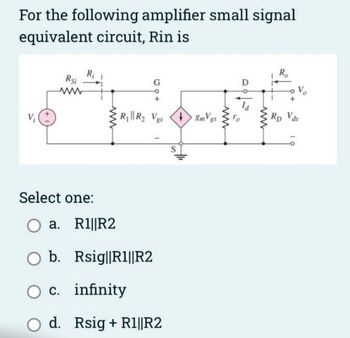
Transcribed Image Text:For the following amplifier small signal
equivalent circuit, Rin is
Rsi
www
R₁ R₂ Vgs +8mVgs
Select one:
O a.
b.
O c. infinity
R1||R2
Rsig||R1||R2
d. Rsig + R1||R2
ww
D
ww
R₂
V₂
Rp Vds
Expert Solution
This question has been solved!
Explore an expertly crafted, step-by-step solution for a thorough understanding of key concepts.
Step by stepSolved in 2 steps with 1 images

Knowledge Booster
Learn more about
Need a deep-dive on the concept behind this application? Look no further. Learn more about this topic, electrical-engineering and related others by exploring similar questions and additional content below.Similar questions
- Please state clearly the purpose and function of two sets of capacitors used in the amplifier circuit shown below, a. C7 – C12 b. Circled internal capacitorsarrow_forwardPlease answer in typing format please ASAP for the like please clear the solution Please answer all subpartarrow_forward24 3 Vsige VGG I RO RS VAP Vout Rout Consider the mosFET Circuit Shown In which &p=3-3 kuz Ac and Rs=4702. The Dc Sources VOD and VGG Set gm = 15 MATU Determine the Overall Voltage gan, Cav Determine the 2 Determine the F3 Out Put resistance Input resistancearrow_forward
- VoD +12 V For the circuit of the adjacent figure a) Given that Ip = 2.83 mA, VGS(om=-7 V and Ipss = 8 mA , find VDs and VGs.. b) If a 50 mV rms input signal is applied to the amplifier, what is the peak-to-peak output voltage? gm = 5000 µS. c) Calculate the output resistance. %3D Ro 10AF 0.1 uF R 10 L. Ra 10 MA 10kn ID= 2.83 mA, Vas (Oef)=-7V. %3Darrow_forwardVCC R2 RC- RI RL R1 RE VEE Assume: B=100, VA=150, Vcc=12V, VEE=GND, Rr=2K, R1=160K, R2=300K, RE=3K, Rc=2.2K, and R1=100K. Convert the circuit to a common-collector circuit. Draw the new circuit (assume the same values for the input and load resistances). Then compute the terminal voltage gain, and Rin (for the whole circuit), re-computing any parameters that you need to solve.arrow_forwardWhat is an active load circuit for amplifier? What is a driver circuit? What makes this unbalanced?arrow_forward
- Please solve with steps, using to study. Will upvote!arrow_forwardB. Make a sketch of the channel region when VGS=VGS-OFF and make a sketch of the channel region when ID=IDSS and explain why each channel has this shape. C. Assuming that the measured values for the PF5102 were VGS-OFF= -1V and IDSs 10mA, design a common source amplifier for ID=4mA and VDS= 4V using a 12V supply and combination biasing without degeneration as you did in the laboratory. D. Find the input resistance, output resistance, and voltage amplification of your design using the hybrid-pi model and explain how you measured these parameters in the laboratory.arrow_forwardsome one solved it but, I think there is a mistake. can you please just solve number 4 and 5arrow_forward
- Derive the output resistance using small signal model for the following circuits, assuming the transistor has output resistance of a transistor is ro and transconductance of gm. Rout PPA Rout Vb- Vbo Rout Rout Vdd Vb- Routarrow_forwardWhat are resistors for? What are capacitors for? What are transistors for? What are Operational amplifiers for? What are oscilloscope for?arrow_forwardHow did they get case 1 and case 2 and simplify break down for a dummy?arrow_forward
arrow_back_ios
arrow_forward_ios
Recommended textbooks for you
 Introductory Circuit Analysis (13th Edition)Electrical EngineeringISBN:9780133923605Author:Robert L. BoylestadPublisher:PEARSON
 Delmar's Standard Textbook Of ElectricityElectrical EngineeringISBN:9781337900348Author:Stephen L. HermanPublisher:Cengage Learning
 Programmable Logic ControllersElectrical EngineeringISBN:9780073373843Author:Frank D. PetruzellaPublisher:McGraw-Hill Education
 Fundamentals of Electric CircuitsElectrical EngineeringISBN:9780078028229Author:Charles K Alexander, Matthew SadikuPublisher:McGraw-Hill Education
 Electric Circuits. (11th Edition)Electrical EngineeringISBN:9780134746968Author:James W. Nilsson, Susan RiedelPublisher:PEARSON
 Engineering ElectromagneticsElectrical EngineeringISBN:9780078028151Author:Hayt, William H. (william Hart), Jr, BUCK, John A.Publisher:Mcgraw-hill Education,

Introductory Circuit Analysis (13th Edition)
Electrical Engineering
ISBN:9780133923605
Author:Robert L. Boylestad
Publisher:PEARSON

Delmar's Standard Textbook Of Electricity
Electrical Engineering
ISBN:9781337900348
Author:Stephen L. Herman
Publisher:Cengage Learning

Programmable Logic Controllers
Electrical Engineering
ISBN:9780073373843
Author:Frank D. Petruzella
Publisher:McGraw-Hill Education

Fundamentals of Electric Circuits
Electrical Engineering
ISBN:9780078028229
Author:Charles K Alexander, Matthew Sadiku
Publisher:McGraw-Hill Education

Electric Circuits. (11th Edition)
Electrical Engineering
ISBN:9780134746968
Author:James W. Nilsson, Susan Riedel
Publisher:PEARSON

Engineering Electromagnetics
Electrical Engineering
ISBN:9780078028151
Author:Hayt, William H. (william Hart), Jr, BUCK, John A.
Publisher:Mcgraw-hill Education,