
Introductory Circuit Analysis (13th Edition)
13th Edition
ISBN: 9780133923605
Author: Robert L. Boylestad
Publisher: PEARSON
expand_more
expand_more
format_list_bulleted
Related questions
Question
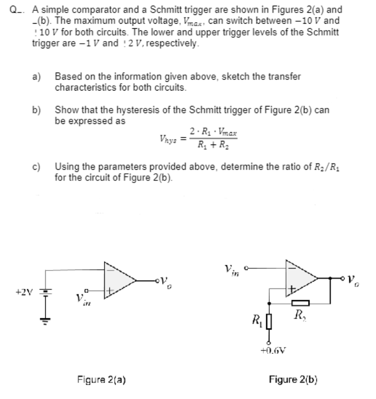

Transcribed Image Text:Q_. A simple comparator and a Schmitt trigger are shown in Figures 2(a) and
_(b). The maximum output voltage, Vmax, can switch between -10 V and
! 10 V for both circuits. The lower and upper trigger levels of the Schmitt
trigger are -1 V and 12 V, respectively.
a)
b)
Based on the information given above, sketch the transfer
characteristics for both circuits.
+2V
Show that the hysteresis of the Schmitt trigger of Figure 2(b) can
be expressed as
c)
Using the parameters provided above, determine the ratio of R₂/R₁
for the circuit of Figure 2(b).
1₂
Vhys =
Figure 2(a)
2.R₁-Vmax
R₁ + R₂
V₂
KŲ
+0.6V
R₂
Figure 2(b)
Tºv.
Expert Solution
This question has been solved!
Explore an expertly crafted, step-by-step solution for a thorough understanding of key concepts.

Step by stepSolved in 4 steps with 3 images

Knowledge Booster


Learn more about
Need a deep-dive on the concept behind this application? Look no further. Learn more about this topic, electrical-engineering and related others by exploring similar questions and additional content below.Similar questions
- What is the DC gain of the given circuit above?arrow_forwardA type II compensator implementation for the above Buck converter is shown below. Ce2 Vout Cet HH Ret Vctrl R2 E/A Vset What should be the voltage Vref in the above type II compensator to produce 5V DC output if R# = 4k and R2=1k. а. Vet b. Write the small signal gain equation (-ctrl) between Vetrl and Vout- out с. Does R2 present in the above gain equation. Please add some explanation. d. How many poles and how many zeros are produced by this type II compensator?arrow_forwardIn a Wien bridge oscillator circuit, the value of the resistor andnthe capacitor that form the RC series and parallel branch are given as 200 ohm and 10 mF. What will be the frequency of oscillation?arrow_forward
arrow_back_ios
arrow_forward_ios
Recommended textbooks for you
- Introductory Circuit Analysis (13th Edition)Electrical EngineeringISBN:9780133923605Author:Robert L. BoylestadPublisher:PEARSON
 Delmar's Standard Textbook Of ElectricityElectrical EngineeringISBN:9781337900348Author:Stephen L. HermanPublisher:Cengage Learning
 Programmable Logic ControllersElectrical EngineeringISBN:9780073373843Author:Frank D. PetruzellaPublisher:McGraw-Hill Education
  Fundamentals of Electric CircuitsElectrical EngineeringISBN:9780078028229Author:Charles K Alexander, Matthew SadikuPublisher:McGraw-Hill Education
 Electric Circuits. (11th Edition)Electrical EngineeringISBN:9780134746968Author:James W. Nilsson, Susan RiedelPublisher:PEARSON
 Engineering ElectromagneticsElectrical EngineeringISBN:9780078028151Author:Hayt, William H. (william Hart), Jr, BUCK, John A.Publisher:Mcgraw-hill Education,
Introductory Circuit Analysis (13th Edition)
Electrical Engineering
ISBN:9780133923605
Author:Robert L. Boylestad
Publisher:PEARSON
Delmar's Standard Textbook Of Electricity
Electrical Engineering
ISBN:9781337900348
Author:Stephen L. Herman
Publisher:Cengage Learning
Programmable Logic Controllers
Electrical Engineering
ISBN:9780073373843
Author:Frank D. Petruzella
Publisher:McGraw-Hill Education
Fundamentals of Electric Circuits
Electrical Engineering
ISBN:9780078028229
Author:Charles K Alexander, Matthew Sadiku
Publisher:McGraw-Hill Education
Electric Circuits. (11th Edition)
Electrical Engineering
ISBN:9780134746968
Author:James W. Nilsson, Susan Riedel
Publisher:PEARSON
Engineering Electromagnetics
Electrical Engineering
ISBN:9780078028151
Author:Hayt, William H. (william Hart), Jr, BUCK, John A.
Publisher:Mcgraw-hill Education,