
Introductory Circuit Analysis (13th Edition)
13th Edition
ISBN: 9780133923605
Author: Robert L. Boylestad
Publisher: PEARSON
expand_more
expand_more
format_list_bulleted
Related questions
Question
not use ai please
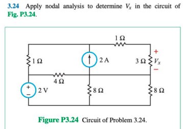

Transcribed Image Text:3.24 Apply nodal analysis to determine V, in the circuit of
Fig. P3.24.
ΣΙΩ
+1
2V
ww
402
ΙΩ
ww
+
⑪2A
2 A
30Vx
80
8Ω
Figure P3.24 Circuit of Problem 3.24.
Expert Solution
This question has been solved!
Explore an expertly crafted, step-by-step solution for a thorough understanding of key concepts.

Step by stepSolved in 2 steps with 1 images

Knowledge Booster

Similar questions
- Ministry of Manpower Directorate General of Technological Education Salalah College of Technology Zlectrical Inginearina Problem - 8 Refer to the circuit below and -25V C2 N. compute the following: i) Total capacitance ii) Voltage across C, iii)Charge across C, iv)Voltage across C5 5 uF C1 5 uF 5 uF C4 5 uF C6 5 uF -16-65V. C5 5 uF (Take V, as 25V) 8-35V VT 25Varrow_forwardA circuit is designed with an AC source of max voltage 12 and frequency 60 Hz. The circuit has a resistance of 1050 Ohms, an inductance of 0.06 Henrys, and a capacitance of 0.009 coulombs per volt. - omega for source in rad/s? - omegaR for circuit? -XL? -XC? -phi in radians? -Z? -imax?arrow_forwardConsider the series-parallel circuit shown in the figure below with various multimeters connected in the circuit. Assum that XMM1 has been configured in ammeter mode, and XMM2 has been configured in voltmeter mode. XMM1 R1 1kQ XMM2 R2 R3 V1 1kQ 1kQ 12V 3.1: Redraw the circuit replacing XMM1 and XMM2 by their equivalent circuit models 3.2: Assume that XMM2 was incorrectly configured in ammeter mode. Redraw the equivalent circuit from 3.1 and compute the current that would be measured by the ammeter in this scenario. Hil-arrow_forward
- for the given circuit find p & q for the load as shownarrow_forward2. Find the state-space representation in phase-variable form for the system shown in Figure P3.8. R(s) 30 55+854 +95³ +6s²+s+ 30 FIGURE P3.8 C(s)arrow_forward2) a. For the circuit shown below, use the Branch Current Method to find an expression for i3 in terms of the circuit components. [ ans: i3 = -Va (R1 + R2)/ (RI R2 + R2 R3 +RI R3) ] b. Do at least two ranging checks on the answer of part a. c. Evaluate the voltage across R3 for the component values given. | ans: v = - 600 mV ] R, Values: Va = 1.0 v R1 = 100 2 R3 R2 = 200 2 R3 = 100 2 a. Use the Branch Current Method to derive an expression for v3 in the circuit below in terms of the other parameters of the circuit. (Hint: Solve for iz first.) W- R, ww | V,R, - V,(R, +R2)], V3= R3 R,R2 +R;R3+R,R3 [ans: b. Perform a units check on this equation. c. Perform one ranging check on this equation. wwarrow_forward
- Below is a circuit diagram. Create a set of equations by using mesh analysis. The value of Rnsid is equal to 625. Express the final answer as rectangular coordinates.arrow_forwardUsing the supernode concept to determine the voltage marked v20 in the figure, the crossed wires that are not marked by a thick dot are not in physical contact.arrow_forwardO Given the information appearing in the Figure, Fird the level of resistance for Ri e R3. RI 3 o 14V Rgarrow_forward
- P7arrow_forwardRA R3 V2 D. R2 R1 For the above circuit, select ALL the extraordinary nodes that are part of a quasi-supernode. If there are none then select NONE. Note: a supernode is not a quasi-supernode. O NONE B. ODOarrow_forwardConvert the computed TEC into NEC. THEVENIN'S EQUIVALENT CIRCUIT (TEC) VTH RTH R3 (Load) NORTON'S EQUIVALENT CIRCUIT (NEC) IN RN R3 (Load)arrow_forward
arrow_back_ios
SEE MORE QUESTIONS
arrow_forward_ios
Recommended textbooks for you
- Introductory Circuit Analysis (13th Edition)Electrical EngineeringISBN:9780133923605Author:Robert L. BoylestadPublisher:PEARSON
 Delmar's Standard Textbook Of ElectricityElectrical EngineeringISBN:9781337900348Author:Stephen L. HermanPublisher:Cengage Learning
 Programmable Logic ControllersElectrical EngineeringISBN:9780073373843Author:Frank D. PetruzellaPublisher:McGraw-Hill Education
  Fundamentals of Electric CircuitsElectrical EngineeringISBN:9780078028229Author:Charles K Alexander, Matthew SadikuPublisher:McGraw-Hill Education
 Electric Circuits. (11th Edition)Electrical EngineeringISBN:9780134746968Author:James W. Nilsson, Susan RiedelPublisher:PEARSON
 Engineering ElectromagneticsElectrical EngineeringISBN:9780078028151Author:Hayt, William H. (william Hart), Jr, BUCK, John A.Publisher:Mcgraw-hill Education,
Introductory Circuit Analysis (13th Edition)
Electrical Engineering
ISBN:9780133923605
Author:Robert L. Boylestad
Publisher:PEARSON
Delmar's Standard Textbook Of Electricity
Electrical Engineering
ISBN:9781337900348
Author:Stephen L. Herman
Publisher:Cengage Learning
Programmable Logic Controllers
Electrical Engineering
ISBN:9780073373843
Author:Frank D. Petruzella
Publisher:McGraw-Hill Education
Fundamentals of Electric Circuits
Electrical Engineering
ISBN:9780078028229
Author:Charles K Alexander, Matthew Sadiku
Publisher:McGraw-Hill Education
Electric Circuits. (11th Edition)
Electrical Engineering
ISBN:9780134746968
Author:James W. Nilsson, Susan Riedel
Publisher:PEARSON
Engineering Electromagnetics
Electrical Engineering
ISBN:9780078028151
Author:Hayt, William H. (william Hart), Jr, BUCK, John A.
Publisher:Mcgraw-hill Education,