
Introductory Circuit Analysis (13th Edition)
13th Edition
ISBN: 9780133923605
Author: Robert L. Boylestad
Publisher: PEARSON
expand_more
expand_more
format_list_bulleted
Related questions
Concept explainers
Question
The two loads in the circuit shown can be described as follows: Load 1 absorbs 8 kW at a leading power factor of 0.8. Load 2 absorbs 20
kVA at a lagging power factor of 0.6.
1. Determine the power factor of the two loads in parallel.
2. Determine the apparent power required to supply the loads, the
magnitude of the current, Is, and the average power loss in thetransmission line.
3. Given that the frequency of the source is 60 Hz, compute the value of
the capacitor that would correct the power factor to 1 if placed in
parallel with the two loads. Recalculate the values in (b) for the load
with the corrected power factor.
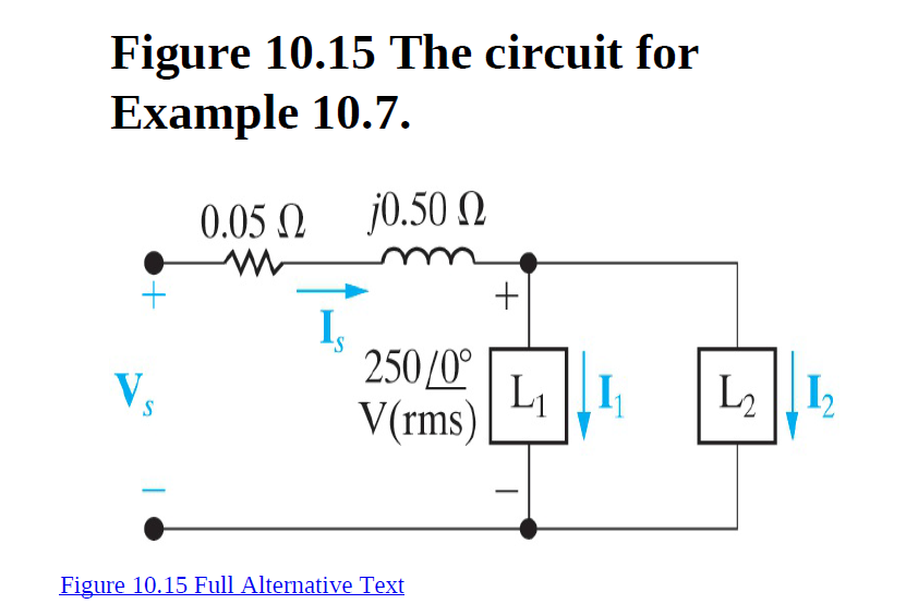

Transcribed Image Text:Figure 10.15 The circuit for
Example 10.7.
0.05 N
j0.50 N
250/0°
V(rms)
Li |[I
L2 |I2
Figure 10.15 Full Alternative Text
Expert Solution
This question has been solved!
Explore an expertly crafted, step-by-step solution for a thorough understanding of key concepts.

This is a popular solution

Trending nowThis is a popular solution!

Step by stepSolved in 10 steps with 11 images

Knowledge Booster


Learn more about
Need a deep-dive on the concept behind this application? Look no further. Learn more about this topic, electrical-engineering and related others by exploring similar questions and additional content below.Similar questions
- Answer the first and last 2 qestion Step By Steparrow_forwardA network is supplied by a 120 V rms, 60-Hz voltage source. An ammeter and a wattmeter indicate that 12 A rms is drawn from the source and 800 W are consumed by the network. Determine: a. The network power factor b. The network phase angle c. The network impedance d. The equivalent resistance and reactance of the networkarrow_forward1 PROBLEM 20020° V rms, Vbn 1. A balanced three-phase Y-Y system has the phase voltages of Van 200/120° V rms, and Ven = 2002(-120°) Vrms. The load impedance per phase is Z₁ = 50 - j100 n. a Van Vcn n Vbn Ia Ib Ic B Zu (b) Determine the line currents Īa, Ip and Īc. (c) Determine the total average power delivered to the three loads. N C = ZL (a) The balanced three-phase circuit has a negative phase sequence. Circle your choice. (1) True (ii) Falsearrow_forward
- The steady-state voltage drop between the load and the sending end of the line seen in (Figure 1) is excessive Suppose that V-4950/0° V (rms). A capacitor is placed in parallel with the 192 kVA load and is adjusted until the steady-state voltage at the sending end of the line has the same magnitude as the voltage at the load end, that is, 4950 V (rms). The 192 kVA load is operating at a power factor of 0.8 lag. Part A Calculate the size of the capacitor in microfarads if the circuit is operating at 60 Hz. In selecting the capacitance, use the value that results in the lowest possible power loss in the line. Express your answer in microfarads to three significant figures. ▸ View Available Hint(s) Figure 1 of 1 202 1100 192 kVA 0.8 lag ΜΕ ΑΣΦ. 11 vec C= 22.8 Submit Previous Answers Incorrect; Try Again; 5 attempts remaining Provide Feedback ? Farrow_forwardGiven: 1. 2 wye-connected loads per phase to a 3 phase power source 2. first load consists of a 55ohm resistance and a 0.05H inductance per phase 3. second load consumes 1kW and power factor of 0.7 lagging per phase 4. RMS of voltage across the loads are 220V, frequency 120Hz per phase 5. single phase equivalent is shown in the figure: Question: What are the RMS line current at load 1 and 2 respectively?arrow_forwardplease explain each part on paper thank you i will likearrow_forward
arrow_back_ios
arrow_forward_ios
Recommended textbooks for you
- Introductory Circuit Analysis (13th Edition)Electrical EngineeringISBN:9780133923605Author:Robert L. BoylestadPublisher:PEARSON
 Delmar's Standard Textbook Of ElectricityElectrical EngineeringISBN:9781337900348Author:Stephen L. HermanPublisher:Cengage Learning
 Programmable Logic ControllersElectrical EngineeringISBN:9780073373843Author:Frank D. PetruzellaPublisher:McGraw-Hill Education
  Fundamentals of Electric CircuitsElectrical EngineeringISBN:9780078028229Author:Charles K Alexander, Matthew SadikuPublisher:McGraw-Hill Education
 Electric Circuits. (11th Edition)Electrical EngineeringISBN:9780134746968Author:James W. Nilsson, Susan RiedelPublisher:PEARSON
 Engineering ElectromagneticsElectrical EngineeringISBN:9780078028151Author:Hayt, William H. (william Hart), Jr, BUCK, John A.Publisher:Mcgraw-hill Education,
Introductory Circuit Analysis (13th Edition)
Electrical Engineering
ISBN:9780133923605
Author:Robert L. Boylestad
Publisher:PEARSON
Delmar's Standard Textbook Of Electricity
Electrical Engineering
ISBN:9781337900348
Author:Stephen L. Herman
Publisher:Cengage Learning
Programmable Logic Controllers
Electrical Engineering
ISBN:9780073373843
Author:Frank D. Petruzella
Publisher:McGraw-Hill Education
Fundamentals of Electric Circuits
Electrical Engineering
ISBN:9780078028229
Author:Charles K Alexander, Matthew Sadiku
Publisher:McGraw-Hill Education
Electric Circuits. (11th Edition)
Electrical Engineering
ISBN:9780134746968
Author:James W. Nilsson, Susan Riedel
Publisher:PEARSON
Engineering Electromagnetics
Electrical Engineering
ISBN:9780078028151
Author:Hayt, William H. (william Hart), Jr, BUCK, John A.
Publisher:Mcgraw-hill Education,