
Introductory Circuit Analysis (13th Edition)
13th Edition
ISBN: 9780133923605
Author: Robert L. Boylestad
Publisher: PEARSON
expand_more
expand_more
format_list_bulleted
Related questions
Question
thumb_up100%
Answer

Transcribed Image Text:C
19:38
Electronics Experiment
1V
2 V
3 V
4 V
5V
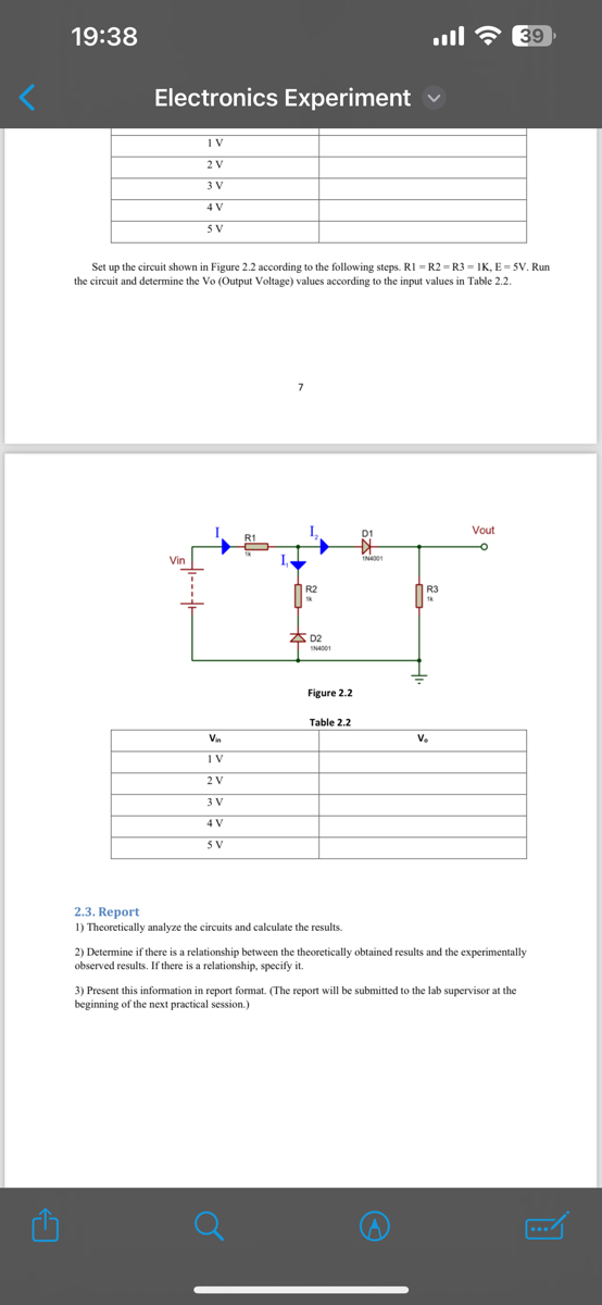
Set up the circuit shown in Figure 2.2 according to the following steps. RI =R2=R3=IK, E=5V. Run
the circuit and determine the Vo (Output Voltage) values according to the input values in Table 2.2.
Vin
1N4001
R3
THE F
D2
Vin
1V
Figure 2.2
Table 2.2
2 V
3 V
4 V
5V
V.
2.3. Report
1) Theoretically analyze the circuits and calculate the results.
2) Determine if there is a relationship between the theoretically obtained results and the experimentally
observed results. If there is a relationship, specify it.
3) Present this information in report format. (The report will be submitted to the lab supervisor at the
beginning of the next practical session.)
貝
Vout
39

Transcribed Image Text:C
19:38
Electronics Experiment
39
Experiment 2: Diode Applications
2.0. Purpose and Scope
In this experiment, circuits using diodes will be examined.
Diode Voltage
Reverse Bias
2.1. Preparations Before the Experiment
a) What is Diode Polarization?
b) How are Diode Voltages Calculated?
2.2. Implementation of the Experiment
Set up the circuit shown in Figure 2.1 according to the following steps. RI - R2 R3 = IK, E=5V. Run
the circuit and determine the Vo (Output Voltage) values according to the input values in Table 2.1.
Vin
R1
R2
D2
1N4001
Figure 2.1
D1
1N4001
Table 2.1
Vin
V.
IV
2 V
3 V
4V
5V
R3
1k
Vout
Set up the circuit shown in Figure 2.2 according to the following steps. RI-R2 R3-IK, E=5V. Run
the circuit and determine the Vo (Output Voltage) values according to the input values in Table 2.2.
Vin
Vout
D1
1N4001
Expert Solution
This question has been solved!
Explore an expertly crafted, step-by-step solution for a thorough understanding of key concepts.

Step by stepSolved in 2 steps with 4 images

Knowledge Booster

Similar questions
arrow_back_ios
arrow_forward_ios
Recommended textbooks for you
- Introductory Circuit Analysis (13th Edition)Electrical EngineeringISBN:9780133923605Author:Robert L. BoylestadPublisher:PEARSON
 Delmar's Standard Textbook Of ElectricityElectrical EngineeringISBN:9781337900348Author:Stephen L. HermanPublisher:Cengage Learning
 Programmable Logic ControllersElectrical EngineeringISBN:9780073373843Author:Frank D. PetruzellaPublisher:McGraw-Hill Education
  Fundamentals of Electric CircuitsElectrical EngineeringISBN:9780078028229Author:Charles K Alexander, Matthew SadikuPublisher:McGraw-Hill Education
 Electric Circuits. (11th Edition)Electrical EngineeringISBN:9780134746968Author:James W. Nilsson, Susan RiedelPublisher:PEARSON
 Engineering ElectromagneticsElectrical EngineeringISBN:9780078028151Author:Hayt, William H. (william Hart), Jr, BUCK, John A.Publisher:Mcgraw-hill Education,
Introductory Circuit Analysis (13th Edition)
Electrical Engineering
ISBN:9780133923605
Author:Robert L. Boylestad
Publisher:PEARSON
Delmar's Standard Textbook Of Electricity
Electrical Engineering
ISBN:9781337900348
Author:Stephen L. Herman
Publisher:Cengage Learning
Programmable Logic Controllers
Electrical Engineering
ISBN:9780073373843
Author:Frank D. Petruzella
Publisher:McGraw-Hill Education
Fundamentals of Electric Circuits
Electrical Engineering
ISBN:9780078028229
Author:Charles K Alexander, Matthew Sadiku
Publisher:McGraw-Hill Education
Electric Circuits. (11th Edition)
Electrical Engineering
ISBN:9780134746968
Author:James W. Nilsson, Susan Riedel
Publisher:PEARSON
Engineering Electromagnetics
Electrical Engineering
ISBN:9780078028151
Author:Hayt, William H. (william Hart), Jr, BUCK, John A.
Publisher:Mcgraw-hill Education,