Database System Concepts
7th Edition
ISBN: 9780078022159
Author: Abraham Silberschatz Professor, Henry F. Korth, S. Sudarshan
Publisher: McGraw-Hill Education
expand_more
expand_more
format_list_bulleted
Question
Using Logism Diagrams would be helpful aswell The Arithmetic Logic Unit The most important and possible most difficult component to implement is the arithmetic logic unit. The
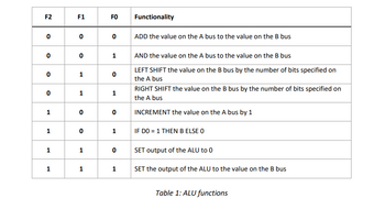
functions of the ALU are shown in Table 1. The ALU should have 5 inputs (A-input, B-input, F0-input, F1-input, Finput) and 1 output (C-output). You will need to determine how many bits each input and output should have.
Remember, you are designing an 8-bit microprocessor! . For example, to add the value on the A-bus
8-bit ALU
to the value on the B-bus, you can simply use an 8-bit adder. Explore the components in Logisim! Additionally,
you can think about using a multiplexer to determine which ALU function will be performed

Transcribed Image Text:F2
F1
FO
Functionality
0
0
0
ADD the value on the A bus to the value on the B bus
0
0
1
AND the value on the A bus to the value on the B bus
0
1
0
0
1
1
LEFT SHIFT the value on the B bus by the number of bits specified on
the A bus
RIGHT SHIFT the value on the B bus by the number of bits specified on
the A bus
INCREMENT the value on the A bus by 1
1
0
0
1
0
1
IF DO = 1 THEN B ELSE O
1
1
0 SET output of the ALU to 0
1
1
1
SET the output of the ALU to the value on the B bus
Table 1: ALU functions

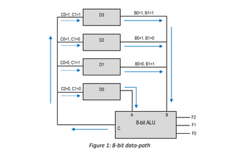
Transcribed Image Text:_ C0=1, C1=1
B0=1, B1=1
D3
CO=1, C1=0
D2
12
B0=1, B1=0
CO=0, C1=1
D1
B0=0, B1=1
C0=0, C1=0
DO
80
C
A
B
F2
8-bit ALU
Figure 1: 8-bit data-path
FO
Expert Solution
This question has been solved!
Explore an expertly crafted, step-by-step solution for a thorough understanding of key concepts.
Step by stepSolved in 1 steps with 7 images

Knowledge Booster
Similar questions
- a- Draw & explain the block diagram of synchronous sequentialcircuits.b- Design & draw a (3 × 2) binary digit multiplier, explaining itsmechanism of operation.arrow_forwardDesign a verilog code for a sequential circuit which has two inputs, w1 and w2, and an output, z. Its function is to compare the input sequences on the two inputs. If w1 = w2 during any four consecutive clock cycles, the circuit produces z = 1; otherwise, z = 0. For example w1 : 0 1 1 0 1 1 1 0 0 0 1 1 0w2 : 1 1 1 0 1 0 1 0 0 0 1 1 1z : 0 0 0 0 1 0 0 0 0 1 1 1 0arrow_forwardUsing Logism Softwarel The most important and possible most difficult component to implement is the 8 bit arithmetic logic unit. Thefunctions of the ALU are shown in Table 1. The ALU should have 5 inputs (A-input, B-input, F0-input, F1-input, Finput) and 1 output (C-output). You will need to determine how many bits each input and output should have.Remember, you are designing an 8-bit microprocessor! . For example, to add the value on the A-bus8-bit ALUto the value on the B-bus, you can simply use an 8-bit adder. Explore the components in Logisim! Additionally,you can think about using a multiplexer to determine which ALU function will be performedarrow_forward
- QUESTION 5 35 A convolutional circuit has three internal registers (s0, s1, and s2), and two outputs (c0 and c1), calculated as follows: c0=i+s2; c1=i+s0+s1. We are currently in state 110 and receive input 0. What is the output and next state? O c0=0; c1=0; next=011 O c0=1; c1=0; next=011 O c0=1; c1=1; next=011 O c0=0; c1=1; next=011 QUESTION 6 11 A convolutional circuit has three internal registers (S0, S1, and s2), and two outputs (c0 and c1), calculated as follows: c0=i+s0; c1=i+s1+s2. We are currently in state 110 and receive input 0. What is the output and next state? O c0=1; c1=1; next=011 O c0=0; c1=1; next=011 O c0=0; c1=0; next=011 O c0=1; c1=0; next=011 QUESTION 7 02 A convolutional circuit has three internal registers (s0, s1, and s2), and two outputs (c0 and c1), calculated as follows: c0=i+s0; c1=i+s0+s1. We are currently in state 011 and receive input 1. What is the output and next state? O c0=0; c1=1; next=101 O c0=0; c1=0; next=101 O c0=1; c1=0; next=101 O c0=1; c1=1;…arrow_forwardWIll make sure to rate thank you! Please complete all parts!arrow_forwardThe circuit below is a 4-bit shifter with 2 control inputs s1 and s0, 4 data inputs 13, 12, 11, and 10, and 4 data outputs Q3, Q2, Q1, and Q0. If the input 13 12 11 10 = 1101, what is the final output when s1 s0 = 01 and then 11 next clock cycle ? 13 12 I1 IO s1 s0 Q3 Q2 Q1 QO 0000 0010 0110 O 1010arrow_forward
- Using Logism for otherwise complete the attached 8 bit alu The Arithmetic Logic Unit The most important and possible most difficult component to implement is the arithmetic logic unit. Thefunctions of the ALU are shown in Table 1. The ALU should have 5 inputs (A-input, B-input, F0-input, F1-input, Finput) and 1 output (C-output). You will need to determine how many bits each input and output should have.Remember, you are designing an 8-bit microprocessor! . For example, to add the value on the A-bus8-bit ALUto the value on the B-bus, you can simply use an 8-bit adder. Explore the components in Logisim! Additionally,you can think about using a multiplexer to determine which ALU function will be performedarrow_forward• Design a sequential circuit with two T Flip Flops, A and B, and two inputs, E and x. If E=0, the circuit remains in the same state regardless of the value of x. When E=1 and x=1, the circuit goes through the state transitions from 00 to 01 to 10 to 11 back to 00, and repeats. When E=1 and x=0, the circuit goes through the state transition from 00 to 11 to 10 to 01 back to 00, and repeatsarrow_forwardDesign and implement (draw the circuit) the output f(12) of a 7 segments decoder as a function of the binary inputs (W,X,Y,Z). You need the complete the following steps: 1. Find the f(12) outputs values (0 or 1) for each number from 0-11 2. Enter these values into a Karnaugh map. 3. Simplify the map. 4. Draw the circuit using Tina. 7 segments display decoder. 7 segments 4 Binary inputs a 7 Segments Decoder Y earrow_forward
- I believe this problem is from computer systems/architecture. PLEASE TRY YOUR BEST. I NEED TO UNDERSTAND THIS PROBLEM I need you to design a digital logic circuit as a read only memory (ROM) [Decoder + OR gates]. A ROM accepts a three–bit number (x2 x1 x0) and generates an output binary number equal to the input squared + 2. Here is the equation: A = x2 + 2, with input (x) : 0 ≤ (x) ≤ 7 (a) Try to set–up the truth–table [Binary inputs: (x); Binary outputs: ..., A2, A1, A0] (b) What is the size of the initial (unsimplified) ROM ? (c) What is the size of the final (simplified) ROM ?arrow_forwardDraw a 4-input adder for single-bit values: that is, a set of logic gates with 4 input wires each representing a number between 0 and 1 and a multi-bit output z, composed of wires z0 through z... (where z0 is the low-order bit, z1 the next, etc., up to the number of wires needed for this task). The gates should ensure that z = the sum of all four inputs.arrow_forwardHow does the width of a register relate to the number of D-flip-flops used in the circuit? Each register is implemented with one D-flip-flop, regardless of the width of the register. Each bit in the register corresponds to two D-flip-flops. Each bit in the register corresponds to a D-flip-flop, so it is 1-to-1. Since D-flip-flops have a Q and Qn output, you only need 1 D-flip-flop for each bit in the register.arrow_forward
arrow_back_ios
SEE MORE QUESTIONS
arrow_forward_ios
Recommended textbooks for you
 Database System ConceptsComputer ScienceISBN:9780078022159Author:Abraham Silberschatz Professor, Henry F. Korth, S. SudarshanPublisher:McGraw-Hill Education
 Starting Out with Python (4th Edition)Computer ScienceISBN:9780134444321Author:Tony GaddisPublisher:PEARSON
 Digital Fundamentals (11th Edition)Computer ScienceISBN:9780132737968Author:Thomas L. FloydPublisher:PEARSON
 C How to Program (8th Edition)Computer ScienceISBN:9780133976892Author:Paul J. Deitel, Harvey DeitelPublisher:PEARSON
 Database Systems: Design, Implementation, & Manag...Computer ScienceISBN:9781337627900Author:Carlos Coronel, Steven MorrisPublisher:Cengage Learning
 Programmable Logic ControllersComputer ScienceISBN:9780073373843Author:Frank D. PetruzellaPublisher:McGraw-Hill Education

Database System Concepts
Computer Science
ISBN:9780078022159
Author:Abraham Silberschatz Professor, Henry F. Korth, S. Sudarshan
Publisher:McGraw-Hill Education

Starting Out with Python (4th Edition)
Computer Science
ISBN:9780134444321
Author:Tony Gaddis
Publisher:PEARSON

Digital Fundamentals (11th Edition)
Computer Science
ISBN:9780132737968
Author:Thomas L. Floyd
Publisher:PEARSON

C How to Program (8th Edition)
Computer Science
ISBN:9780133976892
Author:Paul J. Deitel, Harvey Deitel
Publisher:PEARSON

Database Systems: Design, Implementation, & Manag...
Computer Science
ISBN:9781337627900
Author:Carlos Coronel, Steven Morris
Publisher:Cengage Learning

Programmable Logic Controllers
Computer Science
ISBN:9780073373843
Author:Frank D. Petruzella
Publisher:McGraw-Hill Education