
Elements Of Electromagnetics
7th Edition
ISBN: 9780190698614
Author: Sadiku, Matthew N. O.
Publisher: Oxford University Press
expand_more
expand_more
format_list_bulleted
Related questions
Concept explainers
Question

Transcribed Image Text:Problem 3
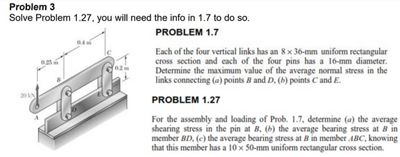
Solve Problem 1.27, you will need the info in 1.7 to do so.
PROBLEM 1.7
04 m
Each of the four vertical links has an 8 x 36-mm uniform rectangular
cross section and each of the four pins has a 16-mm diameter.
Determine the maximum value of the average normal stress in the
links connecting (a) points B and D, (b) points C and E.
0.25
02 m
20 kN
PROBLEM 1.27
For the assembly and loading of Prob. 1.7, determine (a) the average
shearing stress in the pin at B, (b) the average bearing stress at B in
member BD, (c) the average bearing stress at B in member ABC, knowing
that this member has a 10 x 50-mm uniform rectangular cross section.
Expert Solution
This question has been solved!
Explore an expertly crafted, step-by-step solution for a thorough understanding of key concepts.

This is a popular solution

Trending nowThis is a popular solution!

Step by stepSolved in 4 steps with 5 images

Knowledge Booster


Learn more about
Need a deep-dive on the concept behind this application? Look no further. Learn more about this topic, mechanical-engineering and related others by exploring similar questions and additional content below.Similar questions
- THE FRAME SHOWN CONSISTS OF FOUR WOODEN MEMBERS, ABC, DEF,BE, AND CF. KNOWING THAT EACH MEMBER HAS A 50X100MM RECTANGULAR CROSS SECTION AND THAT EACH PIN HAS A 13 MM DIAMETER, DETERMINE THE MAXIMUM VALUE OF THE AVERAGE NORMAL STRESS (A) INMEMBER BE, (B) IN MEMBER CF. 1.125 mm 750 mm V2.160 N 100 mm 100 mm 1.000 mm 375 mm 750 mmarrow_forward1.25 ft 3. Determine the maximum allowable weight of passengers on the gondola ride which is suspended from roller E. The down arm EA is made from 1.5" square solid steel with an allowable normal stress of 18 ksi. The center of roller E to the center of section DC is 1.25'. 4 ft 1.5 in.- B 1.5 in.- 5.5 ft Aarrow_forwardTwo solid cylindrical rods (1) and (2) are joined together at flange B and loaded as shown. If F₁ = 13 kips, F₂ = 34 kips, and the normal stress in each rod must be limited to 22 ksi, determine the minimum diameter d₁ required for rod (1). A (2) d₁ F₂ B C O 1.087 in. O 0.823 in. O 0.541 in. O 0.867 in. O 1.003 in. d₂arrow_forward
- Problem 8.12 A bar of rectangular cross-section, with a width of 60 mm and a thickness of 40 mm, is bent in the shape of a horse shoe having a mean radius of 70 mm. Two equal and opposite forces of 10 kN each are applied at a distance of 12 cm from the centre line of the middle section so that they tend to straighten the rod. Find the maximum ten- sile and compressive stresses and construct a diagram showing the vari- ation of the normal stresses over the central section.arrow_forwardAn annular washer distributes the load P applied to a steel rod to a timber support. The rod's diameter is 22 mm, and the washer's inner diameter is 25 mm, which is larger than the hole's permissible outer diameter. Knowing that the axial normal stress in the steel rod is 35 MPa and the average bearing stress between the washer and the timber must not exceed 5 MPa, examine the smallest allowed outer diameter, d, of the washer. %3D %3D +22 mm P Figure 4arrow_forward1.14 Two hydraulic cylinders are used to control the position of the robotic arm ABC. Knowing that the control rods attached at A and D each have a 20-mm diameter and happen to be parallel in the position shown, determine the average normal stress in (a) member AE, (b) member DG. 400 mm E -300 mm- A F 150 mm 150 mm 200 mm B 600 mm- 800 N Carrow_forward
- Link AC is made of a steel with a 65-ksi ultimate normal stress and has a xin. uniform rectangular cross section. It is connected to a support at A and to member BCD at C by-in.-diameter pins, while member BCD is connected to its support at B by a -in.-diameter pin. All of the pins are made of a steel with a 25-ksi ultimate shearing stress and are in single shear. Knowing that a factor of safety of 3.75 is desired, determine the largest load P that can be applied at D. Note that link AC is not reinforced around the pin holes. 16 IN 8 in 16. ---4 in- The largest load P that can be applied at Dis[ lb.arrow_forwardI need answer within 20 minutes please please with my best wishesarrow_forwardPROBLEM 1.2 Two solid cylindrical rods AB and BC are welded together at B and loaded as shown. Knowing that d = 50 mm and dz = 30 mm, find the average normal stress at the midsection of (a) rod AB, (b) rod BC. 300 mm 40 kN 250 mm V30 KNarrow_forward
arrow_back_ios
arrow_forward_ios
Recommended textbooks for you
- Elements Of ElectromagneticsMechanical EngineeringISBN:9780190698614Author:Sadiku, Matthew N. O.Publisher:Oxford University Press
 Mechanics of Materials (10th Edition)Mechanical EngineeringISBN:9780134319650Author:Russell C. HibbelerPublisher:PEARSON
 Thermodynamics: An Engineering ApproachMechanical EngineeringISBN:9781259822674Author:Yunus A. Cengel Dr., Michael A. BolesPublisher:McGraw-Hill Education
  Control Systems EngineeringMechanical EngineeringISBN:9781118170519Author:Norman S. NisePublisher:WILEY
 Mechanics of Materials (MindTap Course List)Mechanical EngineeringISBN:9781337093347Author:Barry J. Goodno, James M. GerePublisher:Cengage Learning
 Engineering Mechanics: StaticsMechanical EngineeringISBN:9781118807330Author:James L. Meriam, L. G. Kraige, J. N. BoltonPublisher:WILEY
Elements Of Electromagnetics
Mechanical Engineering
ISBN:9780190698614
Author:Sadiku, Matthew N. O.
Publisher:Oxford University Press
Mechanics of Materials (10th Edition)
Mechanical Engineering
ISBN:9780134319650
Author:Russell C. Hibbeler
Publisher:PEARSON
Thermodynamics: An Engineering Approach
Mechanical Engineering
ISBN:9781259822674
Author:Yunus A. Cengel Dr., Michael A. Boles
Publisher:McGraw-Hill Education
Control Systems Engineering
Mechanical Engineering
ISBN:9781118170519
Author:Norman S. Nise
Publisher:WILEY
Mechanics of Materials (MindTap Course List)
Mechanical Engineering
ISBN:9781337093347
Author:Barry J. Goodno, James M. Gere
Publisher:Cengage Learning
Engineering Mechanics: Statics
Mechanical Engineering
ISBN:9781118807330
Author:James L. Meriam, L. G. Kraige, J. N. Bolton
Publisher:WILEY