Elements Of Electromagnetics
7th Edition
ISBN: 9780190698614
Author: Sadiku, Matthew N. O.
Publisher: Oxford University Press
expand_more
expand_more
format_list_bulleted
Concept explainers
Question
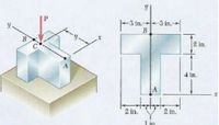
A vertical force P = 15 kip is applied
at point C located on the axis of
symmetry of the cross-section of a
short column.
Given that y = 4.8 in, determine:
a. The stress at points A and B
b. The location of the neutral axis
Note that point C where the force is applied
is not the centroid of the cross section

Transcribed Image Text:-3 in.-
3 in.-
y.
B.
B
2 in.
4 in.
2 in.
2 in.
1 in.
Expert Solution
This question has been solved!
Explore an expertly crafted, step-by-step solution for a thorough understanding of key concepts.
This is a popular solution
Trending nowThis is a popular solution!
Step by stepSolved in 2 steps with 17 images

Knowledge Booster
Learn more about
Need a deep-dive on the concept behind this application? Look no further. Learn more about this topic, mechanical-engineering and related others by exploring similar questions and additional content below.Similar questions
- Please Help me..arrow_forwardWhy is the wall reaction on the left side not considered in the calculation of force Parrow_forwardFor the cantilevered handle shown, the force Fy applied at D is 1000 lbs in the y-direction. Please determine: Make sure you include the stresses due to bending! 1. The loads at point C (identify magnitudes and directions of forces and/or torques and/or moments at point C). 2. The loads at point B (identify magnitudes and directions of forces and/or torques and/or moments at point B). 3. Using the Distortion Energy Theory (DET), determine the STRESS on an element A (see insert). 4. Using the Maximum Shear Stress Theory (MST), determine the STRESS on an element B (see insert).arrow_forward
- 4. Given the beam loaded as below, label the stress blocks for points A and B. A B A Barrow_forward1. When the hand is holding the 5-lb stone, the humerus H, assumed to be smooth, exerts normal forces and on the radius C and ulna A, respectively, as shown. If the smallest cross-sectional area of the ligament at B is 0.30 in?, determine the greatest average tensile stress to which it is subjected. -B FB 75 Fc 0.8 in.l A 2 in. 14 in.arrow_forwardFor the loading arrangement shown, the crate has a weight of 600 lb. The design requirements states that the maximum normal stress (tensile) developed on the cross section a-a should be limited to 13.9 ksi. Determine the maximum value the offset distance "x" to meet this requirement. Develop an appropriate free body diagram and determine the location of the neutral axis for section a-a. X 1 in. Section a - aarrow_forward
- Two solid cylindrical rods (1) and (2) are joined together at flange B and loaded as shown. If F₁ = 13 kips, F₂ = 34 kips, and the normal stress in each rod must be limited to 22 ksi, determine the minimum diameter d₁ required for rod (1). A (2) d₁ F₂ B C O 1.087 in. O 0.823 in. O 0.541 in. O 0.867 in. O 1.003 in. d₂arrow_forwardThe 3/4-in.-diameter shaft is subjected to the loading shown. Determine the stress components at point A. Sketch the results on a volume element located at this point. The journal bearing at C can exert only force components Cyand Cz on the shaft, and the thrust bearing at D can exert force components Dx, Dy, and Dz on the shaft.arrow_forwardThe couple M acts in a vertical plane and is applied to a beam oriented as shown. Determine (a) the angle that the neutral axis forms with the horizontal plane, (b) the maximum tensile stress in the beamarrow_forward
- The axial force in the column supporting the timber beam shown is P = 20 kips. Determine the smallest allowable length L of the bearing plate if the bearing stress in the timber is not to exceed 400 psi.arrow_forwardMember (1) has an area of 2,200.00 mm² and an allowable normal stress of 180.00 MPa. Member (2) has an area of 3,000.00 mm2 and an allowable normal stress of 140.00 MPa. Determine the maximum load P that may be supported by (2) 45° 25° the structure without exceeding either allowable stress. Also, report the force in members (1) and (2) at the maximum load P.arrow_forwardDetermine the STRESS in ksi experienced by the members BC, BG, and FG given the area of its cross section as 1.7 in?. 6 ft-6 ft-6 ft- 6 ft D 6 ft E H 5000 lb 4000 lb 6000 lbarrow_forward
arrow_back_ios
SEE MORE QUESTIONS
arrow_forward_ios
Recommended textbooks for you
 Elements Of ElectromagneticsMechanical EngineeringISBN:9780190698614Author:Sadiku, Matthew N. O.Publisher:Oxford University Press
 Mechanics of Materials (10th Edition)Mechanical EngineeringISBN:9780134319650Author:Russell C. HibbelerPublisher:PEARSON
 Thermodynamics: An Engineering ApproachMechanical EngineeringISBN:9781259822674Author:Yunus A. Cengel Dr., Michael A. BolesPublisher:McGraw-Hill Education
 Control Systems EngineeringMechanical EngineeringISBN:9781118170519Author:Norman S. NisePublisher:WILEY
 Mechanics of Materials (MindTap Course List)Mechanical EngineeringISBN:9781337093347Author:Barry J. Goodno, James M. GerePublisher:Cengage Learning
 Engineering Mechanics: StaticsMechanical EngineeringISBN:9781118807330Author:James L. Meriam, L. G. Kraige, J. N. BoltonPublisher:WILEY

Elements Of Electromagnetics
Mechanical Engineering
ISBN:9780190698614
Author:Sadiku, Matthew N. O.
Publisher:Oxford University Press

Mechanics of Materials (10th Edition)
Mechanical Engineering
ISBN:9780134319650
Author:Russell C. Hibbeler
Publisher:PEARSON

Thermodynamics: An Engineering Approach
Mechanical Engineering
ISBN:9781259822674
Author:Yunus A. Cengel Dr., Michael A. Boles
Publisher:McGraw-Hill Education

Control Systems Engineering
Mechanical Engineering
ISBN:9781118170519
Author:Norman S. Nise
Publisher:WILEY

Mechanics of Materials (MindTap Course List)
Mechanical Engineering
ISBN:9781337093347
Author:Barry J. Goodno, James M. Gere
Publisher:Cengage Learning

Engineering Mechanics: Statics
Mechanical Engineering
ISBN:9781118807330
Author:James L. Meriam, L. G. Kraige, J. N. Bolton
Publisher:WILEY